This model shows an impressive hall frame structure with a curved timber roof of over 60,000 m² in size, realized by Graf-Holztechnik. The primary structure rests on steel and reinforced concrete columns up to 20 m high and uses massive glulam trusses. A record amount of approx. 8,000 m³ of individually calculated, thick, laminated plywood panels allows for a slim and efficient design. Designed by ATP Architects and Engineers in Vienna, Austria, and integrated into a structure designed in RSTAB (© ATP).
| 5 star | ||
| 4 star | ||
| 3 star | ||
| 2 star | ||
| 1 star |
Hall Frame Structure with Curved Timber Roof
| Number of Nodes | 649 |
| Number of Members | 1259 |
| Number of Load Cases | 12 |
| Number of Load Combinations | 828 |
| Number of Result Combinations | 7 |
| Total Weight | 1882,603 t |
| Dimensions (Metric) | 110.732 x 120.924 x 21.360 m |
| Dimensions (Imperial) | 363.29 x 396.73 x 70.08 feet |
| Program Version | 7.04.24 |


After generating the effective lengths, the results are displayed in clearly arranged tables. You can modify the effective lengths manually there.
The Export function transfers the effective lengths to the RF-/TOWER Design add-on module for further calculation. The complete module data are part of the RFEM/RSTAB printout report. The report contents and the extent of the results can be selected specifically for the individual designs.

Finally, it is possible to export the generated model to RFEM/RSTAB with a single mouse click.
The complete module data are part of the RFEM/RSTAB printout report. The report contents and the extent of the results can be selected specifically for the individual designs.

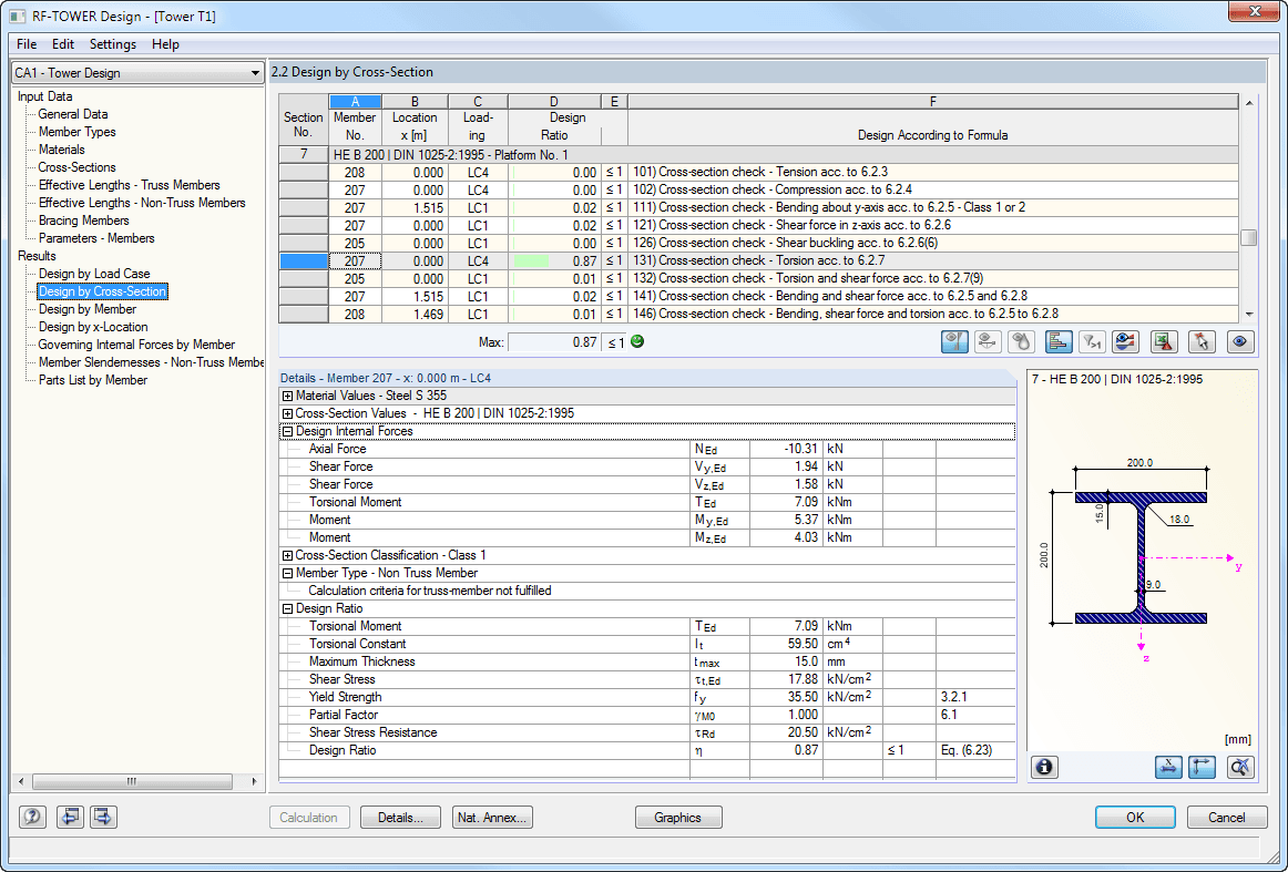
The results are displayed in clearly arranged module windows. In addition to the design data, the results include all design-relevant parameters. A parts list is generated automatically during the calculation.
The complete module data are part of the RFEM/RSTAB printout report. The report contents and the extent of the results can be selected specifically for the individual designs.

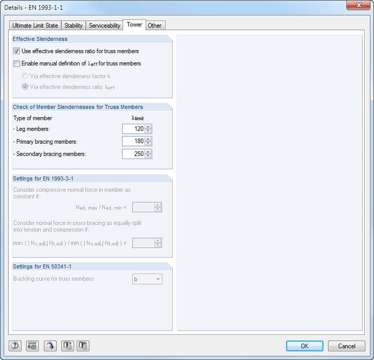
When performing the design of tension, compression, bending, and shear loading, the module compares the design values of the maximum load capacity to the design values of the actions. If the components are subjected to both bending and compression, the program performs an interaction. You can determine the factors according to Method 1 (Annex A) or Method 2 (Annex B).
The flexural buckling design requires neither the slenderness nor the elastic critical buckling load of the governing buckling case. The module automatically calculates all required factors for the bending stress design value. RF-/TOWER Design determines the effective critical moment for lateral-torsional buckling for each member on every x-location of the cross-section.
How can I find RWIND results such as forces data in ParaView?
How can I obtain wind force coefficient in RWIND?


.png?mw=350&hash=f79867dbf405d536638daef39ee25b113e6e540d)


.png?mw=600&hash=49b6a289915d28aa461360f7308b092631b1446e)


