Verification Examples
Dlubal Software programs provide comprehensible structural analysis calculations. They are not a "black box". The verification examples available by clicking the following link provide further transparency into the software calculation methods.
209 Results
View Results:
Sort by:

This example is based on the Atmospheric Boundary Layer (ABL) test from the document of German WTG: Fact Sheet of Committee 3 - Numerical simulation of wind flows, chapter 9.1 (see references). It is an extension of VE0309 - Atmospheric Boundary Layer Test. In this case the rough surface boundary condition is used on the bottom wall and the results are compared with the smooth surface. In the following article, the development of a velocity, turbulence kinetic energy and turbulence dissipation rate is shown for the terrain category 0 defined in the EN 1991-1-4. A vertically anisotropic turbulence acc. to chapter 6.3.1 and RANS k-ω SST turbulence model is used.

A thin plate is fixed on one side (φz=0) and loaded by means of the distributed torque on the other side. First, the plate is modeled as a planar surface. Furthermore, the plate is modeled as one-quarter of the cylinder surface. The planar model's width is equal to the length of one-quarter of the circle of the curved model. The curved model has thus almost equal torsional constant J as the planar model. Determine the maximum rotation of the plate φz,max for both geometrical models and compare the results using both the Kichhoff and the Mindlin plate theory.

Validation in wind engineering is crucial for ensuring the structural integrity of antennas against wind-induced forces. In collaboration with RWTH Aachen University, researchers combine wind tunnel testing and simulations to refine models and enhance accuracy. This study improves antenna resilience, benefiting industries reliant on wind-exposed structures.
This example is based on the atmospheric boundary layer (ABL) test from the document of German WTG: Fact Sheet of Committee 3 - Numerical simulation of wind flows, chapter 9.1 (see references). Before each numerical simulation, it should be checked whether the atmospheric boundary layer defined at the inflow reaches the structure by testing its development in an empty tunnel. This affects not only the distribution of the velocities, but also the turbulent quantities. The test must be carried out for both steady (RANS) and transient (URANS, LES) calculations. In the following article, the development of a velocity field, turbulence kinetic energy field and turbulence dissipation rate field is shown for the four terrain categories I to IV defined in the EN 1991-1-4. A vertically anisotropic turbulence acc. to chapter 6.3.1 and RANS k-ω turbulence model is used.

A cantilever made of the material with different tensile and compressive plastic strength is fully fixed on the left end and loaded by a bending moment according to the following sketch. The problem is described by the following set of parameters. Small deformations are considered and the self-weight is neglected in this example. Determine the maximum deflection uz,max.

Determine the required strengths and effective length factors for the ASTM A992 material columns in the moment frame shown in Figure 1 for the maximum gravity load combination, using LRFD and ASD.

An ASTM A992 W-shaped member is selected to carry a dead load of 30.000 kips and a live load of 90.000 kips in tension. Verify the member strength using both LRFD and ASD.

An ASTM A992 14×132 W-shaped column is loaded with the given axial compression forces. The column is pinned top and bottom in both axes. Determine whether the column is adequate to support the loading shown in Figure 1 based on LRFD and ASD.

Consider an ASTM A992 W 18x50 beam forspan and uniform dead and live loads as shown in Figure 1. The member is limited to a maximum nominal depth of 18 inches. The live load deflection is limited to L/360. The beam is simply supported and continuously braced. Verify the available flexural strength of the selected beam, based on LRFD and ASD.

An ASTM A992 W 24×62 beam with end shears of 48.000 and 145.000 kips from the dead and live loads, respectively, is shown in Figure 1. Verify the available shear strength of the selected beam, based on LRFD and ASD.

Using AISC Manual tables, determine the available compressive and flexural strengths and whether the ASTM A992 W14x99 beam has sufficient available strength to support the axial forces and moments shown in Figure 1, obtained from a second-order analysis that includes P-𝛿 effects.

This verification example is a modification of VE0064 - Thick-Walled Vessel, where the only difference is that the material of the vessel is incompressible. A thick-walled vessel is loaded by inner and outer pressure. The vessel is open-ended, thus there is no axial stress. The problem is modeled as a quarter model and described by the following set of parameters. While neglecting self-weight, determine the radial deflection of the inner and outer radius ur(r1), ur(r2).

A thick-walled vessel is loaded by inner pressure, which is chosen so that the vessel reaches the elastic-plastic state. The problem is modeled as a quarter model. While neglecting self-weight, determine and compare the analytical and numerical solution for the radial position of the plastic zone border ry under the Tresca hypothesis for the yield surface.

A two-layered thick-walled vessel is loaded by inner and outer pressure. The vessel is open, thus there is no axial stress. The problem is modeled as a quarter model. Determine the radial deflection of the inner and outer radius ur(r1), ur(r2) and the pressure (radial stress) in the middle radius pm. The self-weight is neglected.

A thick-walled vessel is loaded by inner and outer pressure. The vessel is open-ended, thus there is no axial stress. The problem is modeled as a quarter model. Determine the radial deflection of the inner and outer radius ur(r1), ur(r2). The self-weight is neglected.

A compact disc (CD) rotates at a speed of 10,000 rpm. Therefore, it is subjected to centrifugal force. The problem is modeled as a quarter model. Determine the tangential stress σt on the inner and outer diameters and the radial deflection ur of the outer radius.

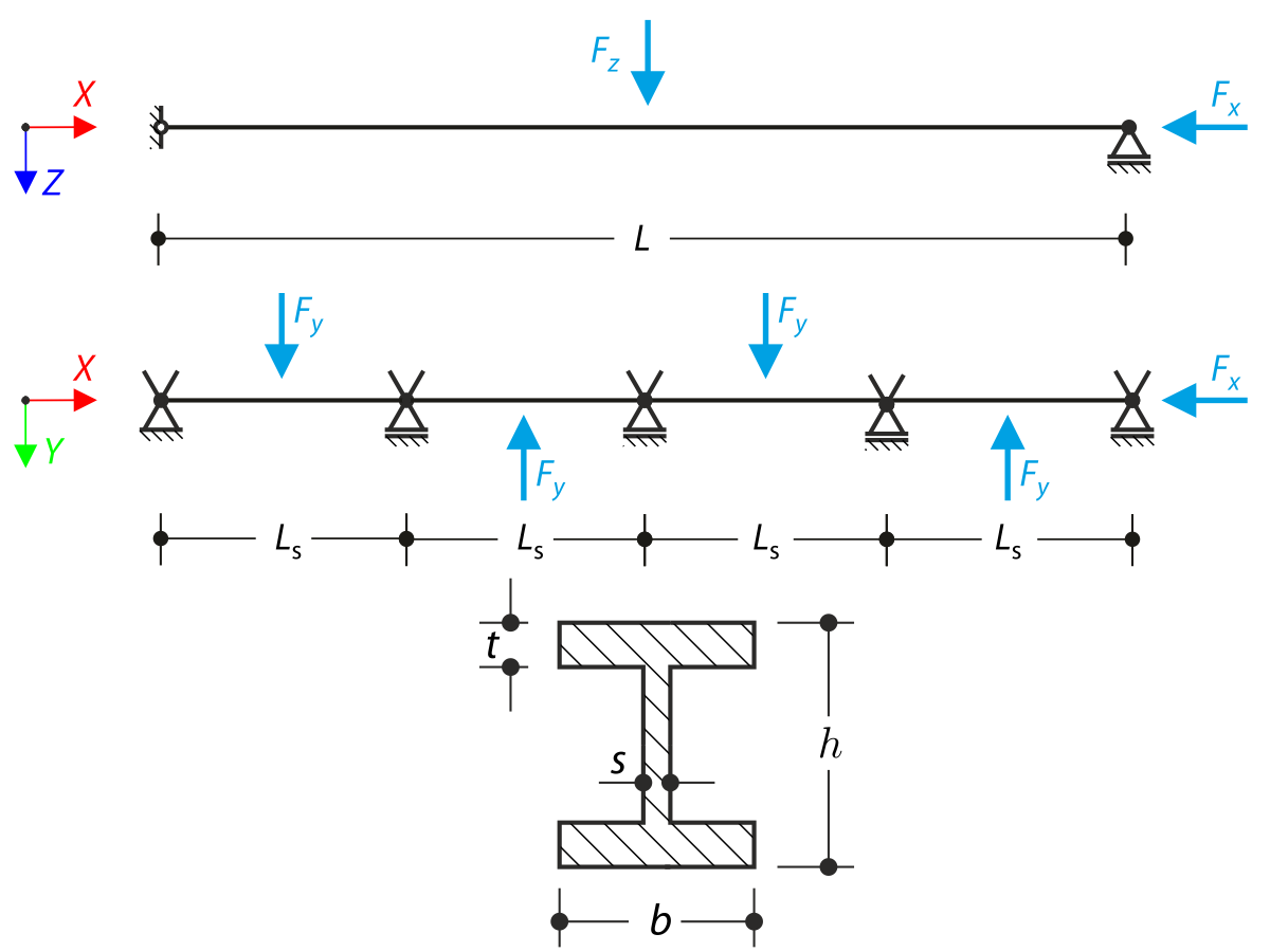
A structure consists of I-profile simply supported beam. The axial rotation φx is restricted on the both ends but the cross-section is free to warp (fork support). The beam has an initial imperfection in Y-direction defined as a parabolic curve with maximum displacement 30 mm in the middle. Uniform loading is applied in the middle of the top flange of I-profile. The problem is described by the following set of parameters. The verification example is based on the example introduced by Gensichen and Lumpe.

A structure is consisted of an I-section beam and two tube trusses. The structure contains several imperfections and it is loaded by the force Fz. The self-weight is neglected in this example. Determine the deflections uy and uz and axial rotation φx at the endpoint (Point 4). The verification example is based on the example introduced by Gensichen and Lumpe.

In this verification example the punching shear resistance of an inner column of a flat slab is examined. The column has a circular secton with a 30cm diameter.
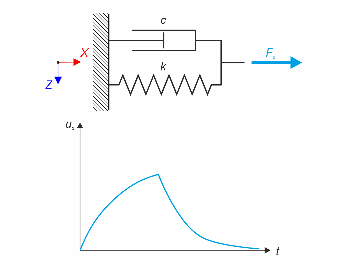
Kelvin-Voigt material model consists of the linear spring and viscous damper connected in parallel. In this verification example there is tested the time behaviour of this model during the loading and relaxation in a time interval 24 hours. The constant force Fx is applied for 12 hours and the rest 12 hours is the material model free of load (relaxation). The deformation after 12 and 20 hours is evaluated. Time History Analysis with Linear Implicit Newmark method is used.
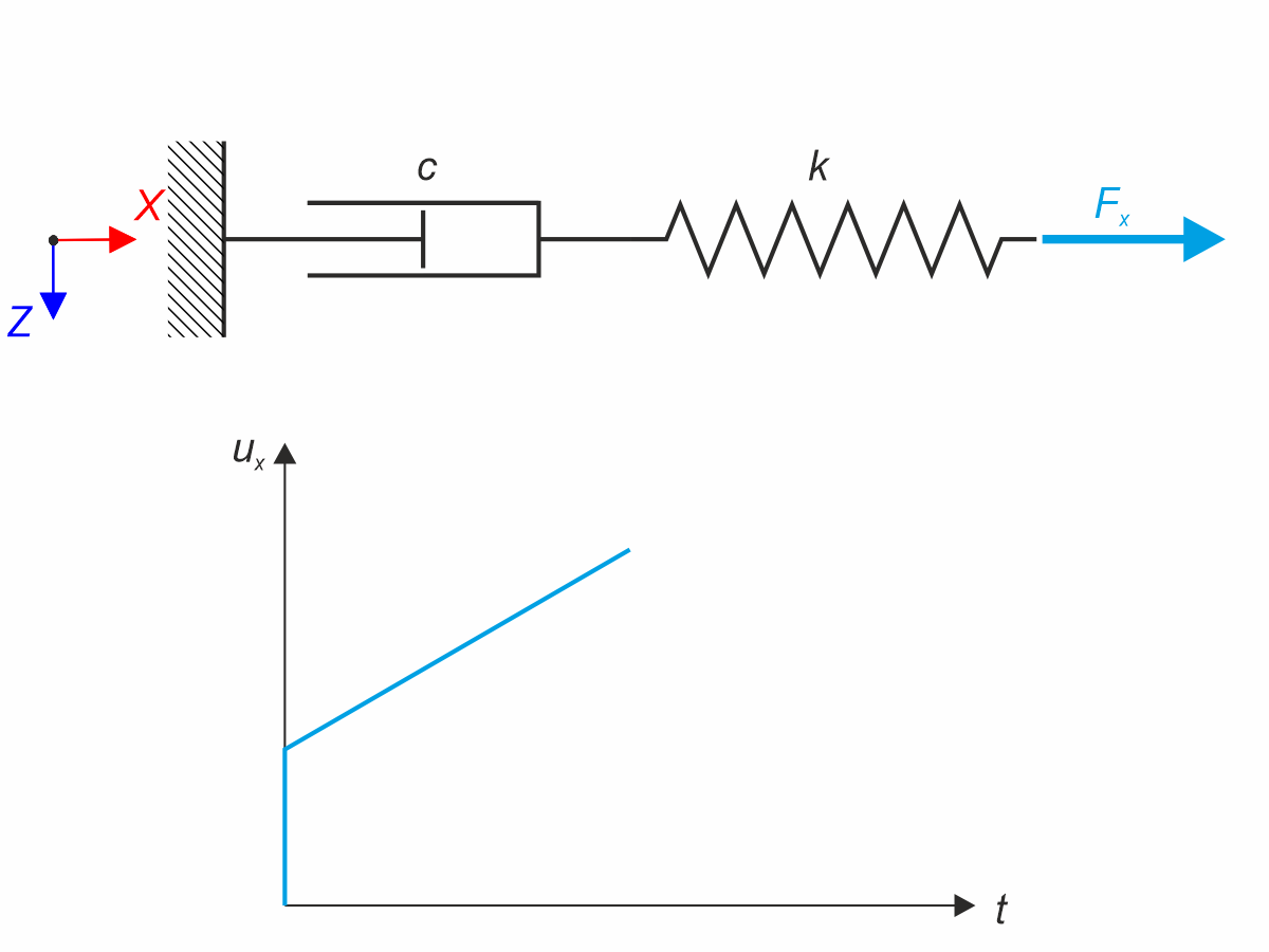
Maxwell material model consists of the linear spring and viscous damper connected in series. In this verification example there is tested the time behaviour of this model. The Maxwell material model is loaded by constant force Fx. This force causes initial deformation thanks to the spring, the deformation is then growing in time due to the damper. The deformation is observed at time of loading (20 s) and at the end of the analysis (120 s). Time History Analysis with Linear Implicit Newmark method is used.

A collar beam roof with the selected geometry is compared in terms of its internal forces between the calculation using RFEM 6 and the manual calculation. In total, three load systems are analyzed.
Continuous beam with four spans is loaded by axial and bending forces (replacing imperfections). All supports are fork - warping is free. Determine displacements uy and uz, moments My, Mz, Mω and MTpri and rotation φx. The verification example is based on the example introduced by Gensichen and Lumpe.

This example compares the effective lengths and critical load factor, which can be calculated in RFEM 6 using the Structure Stability add-on, with a manual calculation. The structural system is a rigid frame with two additional hinged columns. This column is loaded by vertical concentrated loads.
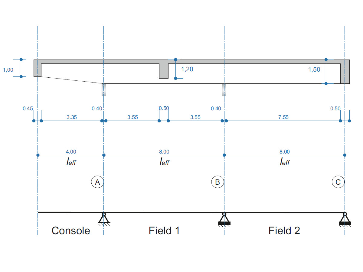
A reinforced concrete beam is designed as a two-span beam with a cantilever. The cross-section varies along the length of the cantilever (tapered cross-section). The internal forces, the required longitudinal and shear reinforcement for the ultimate limit state are calculated.
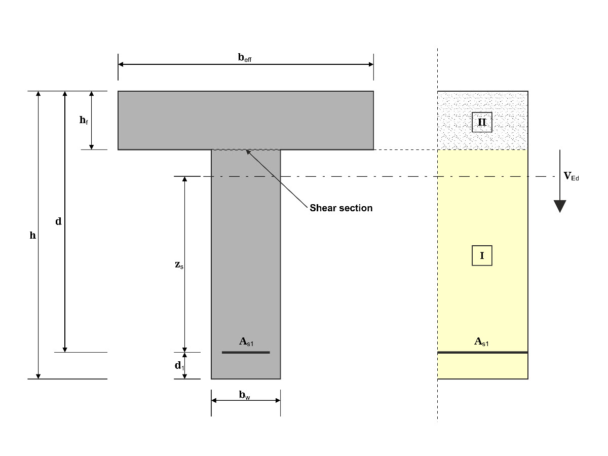
In this example, the shear at the interface between concrete cast at different times and the corresponding reinforcement are determined according to DIN EN 1992-1-1. The obtained results with RFEM 6 will be compared to the hand calculation below.
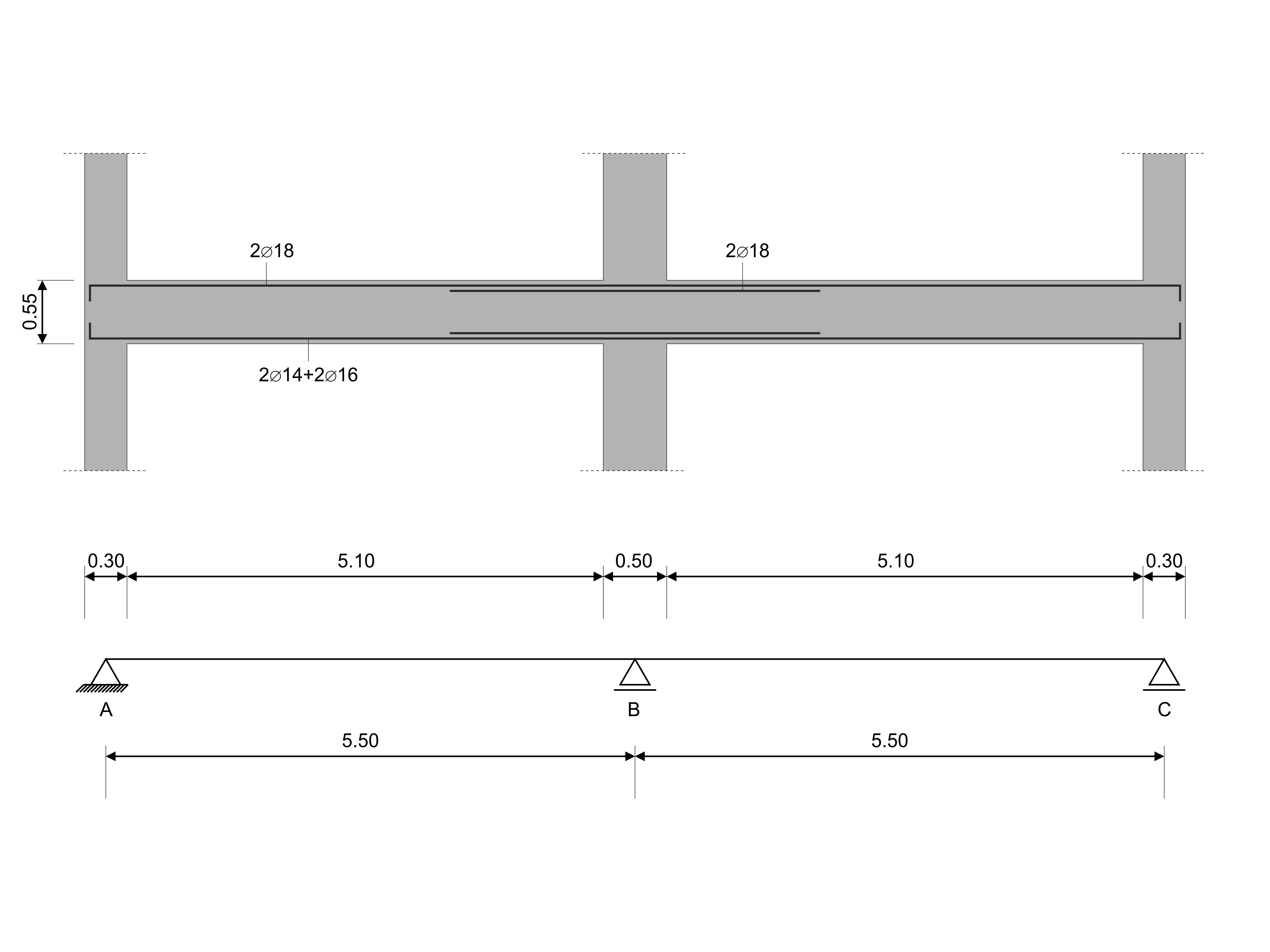
In this verification example, the capacity design values of shear forces on beams are calculated in accordance with EN 1998-1, 5.4.2.2 and 5.5.2.1 as well as the capacity design values of columns in flexure in accordance with 5.2.3.3(2). The system consists of a two span reinforced concrete beam with a span length of 5.50m. The beam is part of a frame system. The results obtained are compared with those in [1].
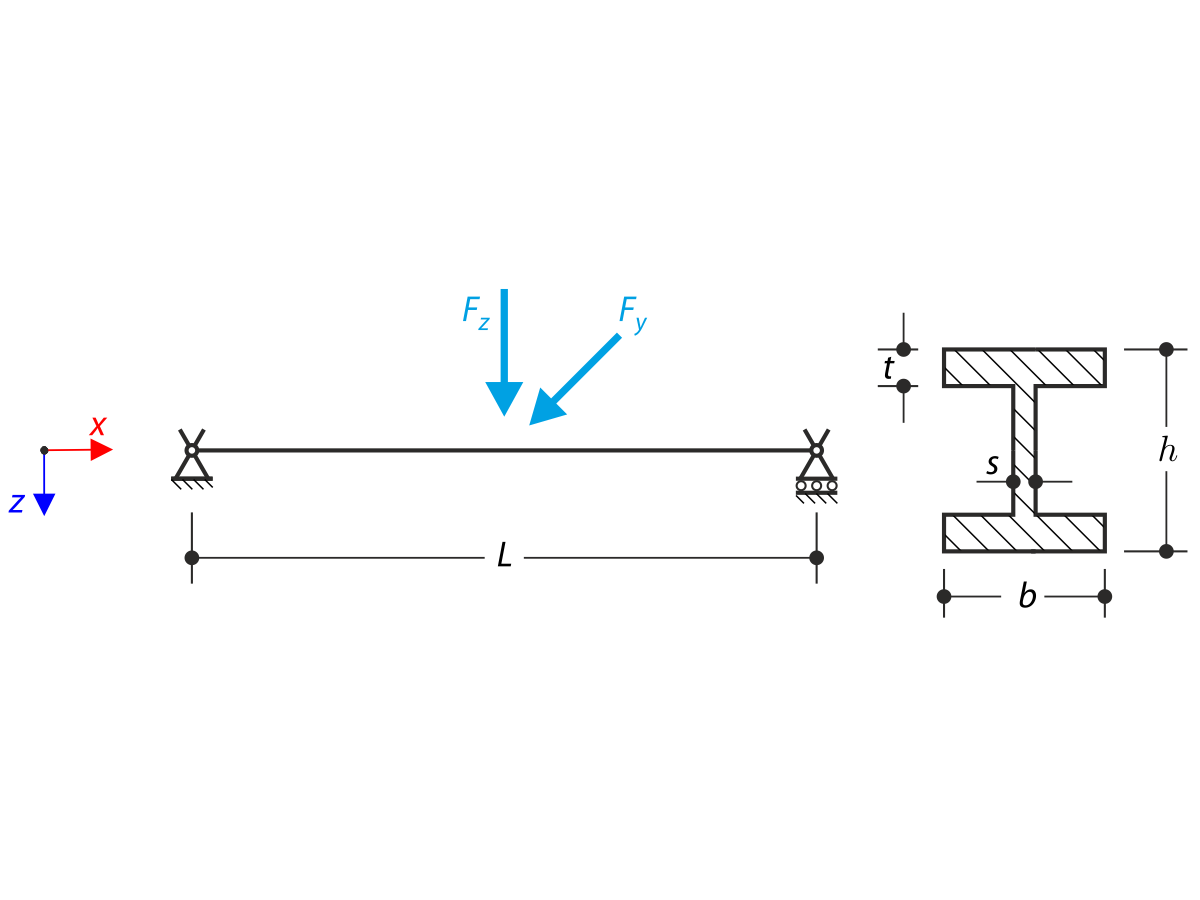
The axial rotation of the I-profile is restricted on the both ends by means of the fork supports (warping is not restricted). The structure is loaded by two transverse forces in its middle. The self-weight is neglected in this example. Determine the maximum deflections of the structure uy,max and uz,max, maximum rotation φx,max, maximum bending moments My,max and Mz,max and maximum torsional moments MT,max, MTpri,max, MTsec,max and Mω,max. The verification example is based on the example introduced by Gensichen and Lumpe.
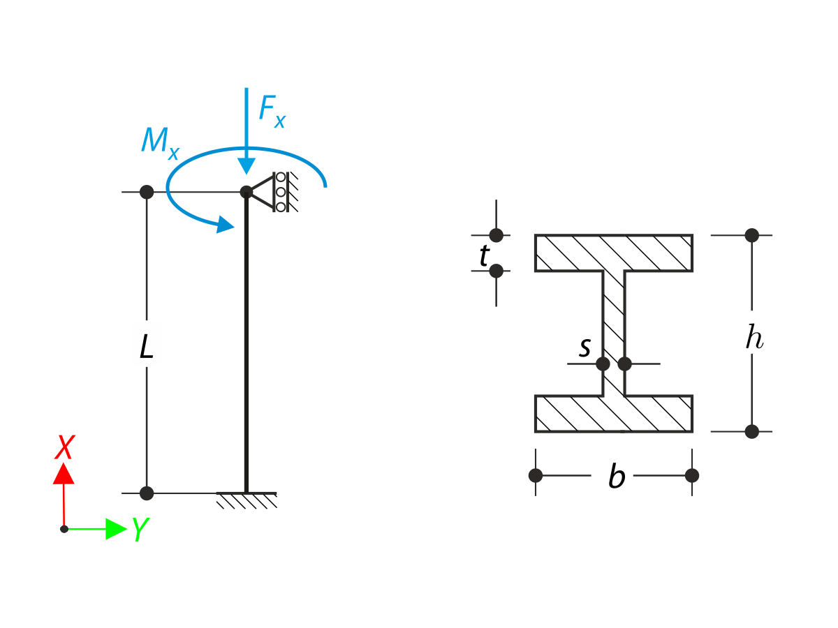
A member with the given boundary conditions is loaded by torsional moment and axial force. Neglecting its self-weight, determine the beam's maximum torsional deformation as well as its inner torsional moment, defined as the sum of a primary torsional moment and torsional moment caused by the normal force. Provide a comparison of those values while assuming or neglecting the influence of the normal force. The verification example is based on the example introduced by Gensichen and Lumpe.
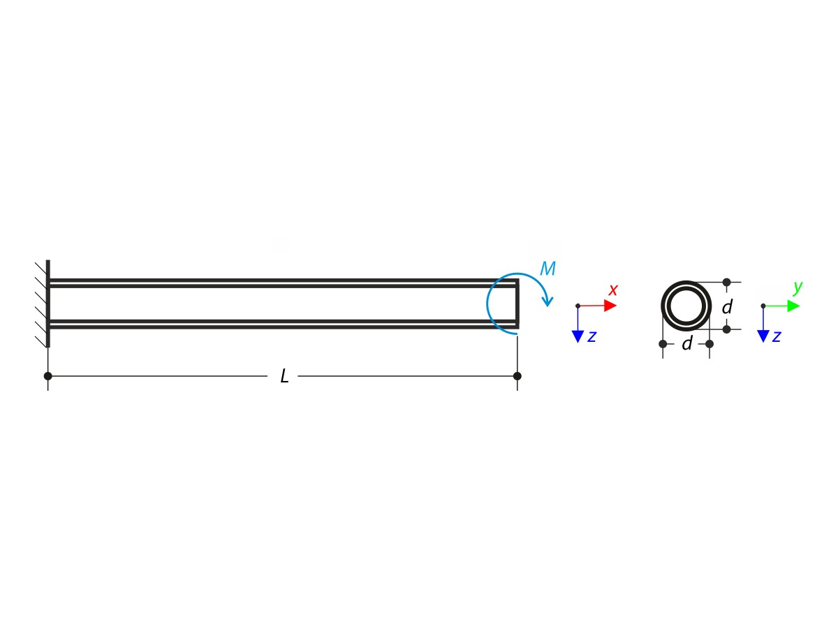
A cantilever is loaded by a moment at its free end. Using the geometrically linear analysis and large deformation analysis, and neglecting the beam's self-weight, determine the maximum deflections at the free end. The verification example is based on the example introduced by Gensichen and Lumpe.