- Free definition of two reinforcement layers
- Design alternatives to avoid compression or shear reinforcement
- Design of surfaces as deep beams (theory of membranes)
- Option to define basic reinforcements for top and bottom reinforcement layers
- Free definition of provided surface reinforcement
- Result output in points of any selected grid
- Design with design moments at column edges
- Determination of deformation in state II; for example, according to EN 1992‑1‑1, 7.4.3, and ACI 318‑19 24.2.3, Table 24.2.3.5
- Considering tension stiffening
- Considering creep and shrinkage
- Fatigue Design According to EN 1992-1-1, Chapter 6.8
- Design of a shear joint between the web and flange of ribs
- Optional pure slab or wall design of surfaces for a 2D model type
- Precise breakdown of reasons for failed design
- Design details of all design locations for better traceability of reinforcement determination
Concrete Design | Members and Surfaces | Surface Design


Duration: 00:00:57 min

Duration: 00:00:58 min

Duration: 00:00:24 min

Duration: 00:00:22 min

Duration: 00:00:31 min

Duration: 00:00:22 min

Duration: 00:00:54 min

Duration: 00:00:56 min

Duration: 01:31:03 min


Dlubal_KohlA_]_LI.jpg?mw=350&hash=21d94ec9a723c608496e9e95a21bb1309ab5067a)


The limit stresses in RF‑/STEEL can be user-defined for each thickness range.
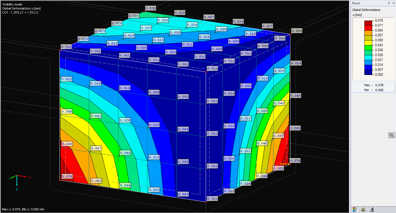
The deformations of the FE nodes are always the first result of an FE calculation. It is possible to calculate strains, internal forces, and stresses based on these deformations and the stiffness of the elements.

This article explores the importance of considering joint-structure interaction in modeling and design and how to do it in RFEM 6.
.png?mw=512&hash=4a84cbc5b1eacf1afb4217e8e43c5cb50ed8d827)
This article provides a comprehensive overview of essential seismic analysis methods, explaining their principles and applications, as well as the scenarios in which they are most effective


_3.jpg?mw=350&hash=6831ba094e54512b3726fc611ff1b3a3f24436b7)


- General stress analysis
- Automatic import of internal forces from RFEM/RSTAB
- Complete graphical and numerical results of stresses and stress ratios integrated in RFEM/RSTAB
- Wide range of customization options for graphical output
- Flexible design in multiple design cases
- Clearly arranged result tables for a quick overview after the design
- High productivity due to the minimal amount of input data required
- Flexibility due to detailed setting options for basis and extent of calculations

- Cross-section optimization
- Transfer of optimized sections to RFEM/RSTAB
- Design of any thin-walled cross-section from SHAPE-THIN
- Representation of a stress diagram on a section
- Determination of normal, shear, and equivalent stresses
- Stress results of individual internal forces types
- Detailed representation of stresses in all stress points
- Determination of the largest Δσ for each stress point (for example, for fatigue design)
- Colored display of stresses and design ratios for a quick overview of the critical or oversized zones
- Parts lists and quantity surveying

- Determination of principal and basic stresses, membrane and shear stresses, as well as equivalent stresses and equivalent membrane stresses
- Stress analysis for structural surfaces including simple or complex shapes
- Equivalent stresses calculated according to different approaches:
- Shape modification hypothesis (von Mises)
- Shear stress hypothesis (Tresca)
- Normal stress hypothesis (Rankine)
- Principal strain hypothesis (Bach)
- Optional optimization of surface thicknesses and data transfer to RFEM
- Serviceability limit state design by checking surface displacements
- Detailed results of individual stress components and ratios in tables and graphics
- Filter function for surfaces, lines, and nodes in tables
- Transversal shear stresses according to Mindlin, Kirchhoff, or user-defined specifications
- Parts list of designed surfaces

In order to facilitate the data input, surfaces, members, sets of members, materials, surface thicknesses, and cross-sections are preset. It is possible to select the elements graphically using the [Select] function. The program provides access to the global material and cross-section libraries.
Load cases, load combinations, and result combinations can be combined in various design cases.
The combination of surface and member elements and separate designs allows you to model and analyze only critical parts, such as frame joints, using surface elements. The other parts of the model can be designed using member analyses.
The design ratio of the cross-section check is different for the RF‑/STEEL and RF‑/STEEL EC3 add-on modules. What can be the cause?
For a buckling analysis, PLATE‑BUCKLING determines the governing shear stress of τ = 7.45 kN/cm², while RF‑/STEEL gives the result of the maximum shear stress of τ = 8.20 kN/cm². Where does this difference come from?
How can I design any SHAPE‑THIN cross-section in detail in RFEM 5 or RSTAB 8?
How can I display the stresses in the stress points in RF‑STEEL Members?
What is the difference between the RF‑/STEEL and RF‑/STEEL EC3 add-on modules?
I am comparing the flexural buckling design according to the equivalent member method and the internal forces according to the linear static analysis with the stress calculation according to the second-order analysis, including imperfections. The differences are very large. What can be the reason for this?


_1.jpg?mw=350&hash=ab2086621f4e50c8c8fb8f3c211a22bc246e0552)


Recommended Products for You
RFEM 6 | Main Program RFEM 6

The new generation of 3D FEA software is used for the structural analysis of members, surfaces, and solids.
Price of First License
4,790.00 USD
RFEM 6 | Design

The Steel Design add-on performs the ultimate and serviceability limit state design checks of steel members according to various standards.
Price of First License
2,970.00 USD
RFEM 6 | Joints
.png?mw=600&hash=49b6a289915d28aa461360f7308b092631b1446e)
The Steel Joints add-on for RFEM allows you to analyze steel connections using an FE model. The FE model is generated automatically in the background and can be controlled via the simple and familiar input of components.
Price of First License
2,670.00 USD
RFEM 6 | Additional Analysis

The Torsional Warping (7 DOF) add-on allows you to consider cross-section warping as an additional degree of freedom.
Price of First License
1,660.00 USD
RFEM 6 | Additional Analysis

The Nonlinear Material Behavior add-on allows you to consider material nonlinearities in RFEM for example, isotropic plastic, orthotropic plastic, isotropic damage).
Price of First License
1,660.00 USD
RFEM 6 | Additional Analysis

The Structure Stability add-on performs stability analysis of structures. It determines critical load factors and the corresponding stability modes.
Price of First License
1,460.00 USD
RFEM 6 | Additional Analysis

The Construction Stages Analysis (CSA) add-on allows for considering the construction process of structures (member, surface, and solid structures) in RFEM.
Price of First License
1,760.00 USD
RFEM 6 | Additional Analysis

The Time-Dependent Analysis (TDA) add-on allows you to consider the time-dependent material behavior of members and surfaces. The long-term effects, such as creep, shrinkage, and aging, can influence the distribution of internal forces, depending on the structure.
Price of First License
1,160.00 USD
RFEM 6 | Additional Analysis

The Form-Finding add-on finds the optimal shape of members subjected to axial forces and tension-loaded surface models. The shape is determined by the equilibrium between the member axial force or the membrane stress and the existing boundary conditions.
Price of First License
2,320.00 USD
RFEM 6 | Dynamic Analysis

The Modal Analysis add-on allows for the calculation of eigenvalues, natural frequencies, and natural periods for member, surface, and solid models.
Price of First License
1,360.00 USD
RFEM 6 | Dynamic Analysis

Using the Pushover Analysis add-on, you can analyze the seismic actions on a particular building, and thus assess whether the building can withstand an earthquake.
Price of First License
1,460.00 USD
RFEM 6 | Special Solutions

The Building Model add-on for RFEM allows you to define and manipulate a building using stories. The stories can be adjusted in many ways afterwards. The information about stories and the entire model (center of gravity) is displayed in tables and graphics.
Price of First License
1,970.00 USD
RFEM 6 | Design

The Stress-Strain Analysis add-on performs general stress analysis by calculating the existing stresses and comparing them with the limit stresses.
Price of First License
1,360.00 USD
RSTAB 9 | Main Program RSTAB 9

The modern 3D structural analysis and design program is suitable for the structural and dynamic analysis of beam structures as well as the design of concrete, steel, timber, and other materials.
Price of First License
3,380.00 USD
RSTAB 9 | Design
The Steel Design add-on performs the ultimate and serviceability limit state design checks of steel members according to various standards.
Price of First License
2,970.00 USD
RSTAB 9 | Additional Analysis
The Structure Stability add-on performs the stability analysis of structures. It determines critical load factors and the corresponding stability modes.
Price of First License
1,460.00 USD
RSTAB 9 | Design
The Stress-Strain Analysis add-on performs a general stress analysis by calculating the existing stresses and comparing them to the limit stresses.
Price of First License
1,260.00 USD
RSTAB 9 | Additional Analysis
The Torsional Warping (7 DOF) add-on allows for considering cross-section warping as an additional degree of freedom when calculating members.
Price of First License
1,660.00 USD
RSTAB 9 | Dynamic Analysis
The Modal Analysis add-on allows for the calculation of eigenvalues, natural frequencies, and natural periods for member, surface, and solid models.
Price of First License
1,360.00 USD
RSTAB 9 | Dynamic Analysis
Earthquakes may have a significant impact on the deformation behavior of buildings. A pushover analysis allows you to analyze the deformation behavior of buildings and compare them with seismic actions. Using the Pushover Analysis add-on, you can analyze the seismic actions on a particular building, and thus assess whether the building can withstand the earthquake.
Price of First License
1,460.00 USD