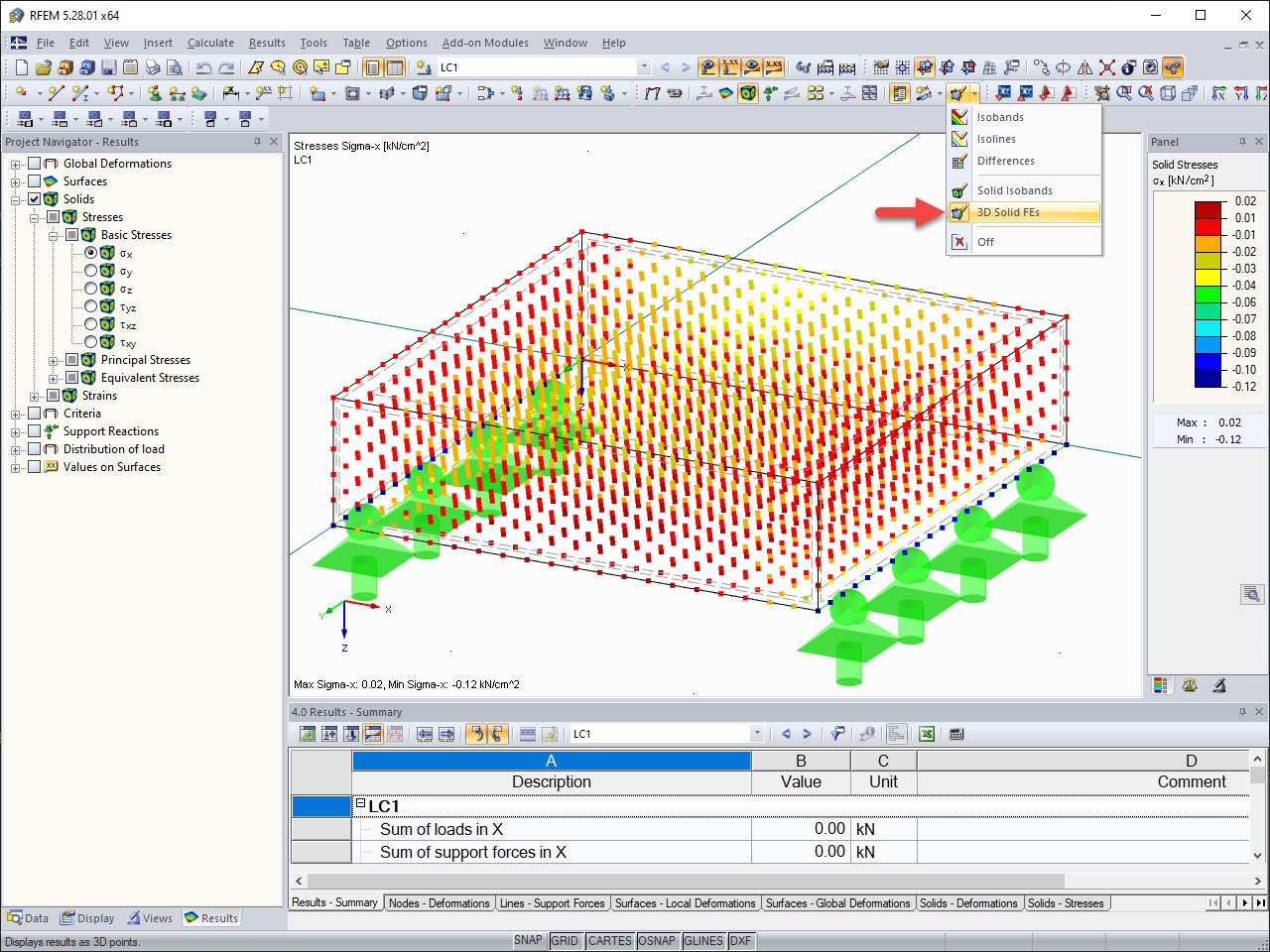
To do this, go to Display Properties (using the shortcut menu, open by right-clicking in the RFEM graphic window) and select "Colors" → "Other" → "Text Bubbles". In the settings for the text bubbles, you will find "Line Thickness". It is preset to "3" by default. If you want to display the red grid points as smaller, set either "1" or "2".
Question
I want to display the results of RF‑CONCRETE Surfaces on grid points transparently, and now I get very large red dots at the grid points. How can I adjust the size?
![RFEM Model with Permanent and Variable Loads](/en/webimage/021543/3083454/01-fr.png?mw=512&hash=5abb1fa9cfbaf68b443ad73b71b313783c0bbec9)
![Design of Shear Joint](/en/webimage/010168/3063348/ENG.png?mw=512&hash=fcc08566226b0d335f8000d284cb96cd5a77894b)
![Adjusting Reinforcement Directly in Graphic Window](/en/webimage/010180/3063138/ENG.png?mw=512&hash=fcc08566226b0d335f8000d284cb96cd5a77894b)
![Fire Resistance Design with CONCRETE and RF-CONCRETE Members](/en/webimage/010240/3058619/1-en.png?mw=512&hash=2f0018b00b526e3852def3f63ee3e343e51b99d4)
![Transfer of Reinforcement from RFEM/RSTAB (Top) to Revit (Bottom)](/en/webimage/006834/526064/Dlubal-Revit.png?mw=512&hash=9a92302ba8b440403caf2f68050db6dc529c1eb1)
The reinforcement proposal from RF-/CONCRETE Members can be exported to Revit. The rectangular and circular cross-sections are currently supported.
The reinforcement bars can be modified retroactively in Revit.
Surface reinforcements defined in the RF-CONCRETE Surfaces add-on module can be exported to Revit as reinforcement objects via the direct interface. To do this, you can optionally select surface, rectangular, polygon, and circular reinforcement areas in RF-CONCRETE Surfaces. In addition to bar reinforcement, it is possible to export mesh reinforcement.
![Feature 002423 | Displaying Results in Solids](/en/webimage/031923/3325382/FE_Solid_EN.jpg?mw=512&hash=d2950a5e2123942fab13aad296e814c67695c955)
The results of solid stresses can be displayed as colored 3D points in the finite elements.
![Improved Calculation Performance by Optimized Consideration of Nodal Degrees of Freedom in RFEM](/en/webimage/015531/2983511/Berechnungsperformance_EN_(1).png?mw=512&hash=ea9bf0ab53a4fb0da5c4ed81d32d53360ab2820c)
The number of degrees of freedom in a node is no longer a global calculation parameter in RFEM (6 degrees of freedom for each mesh node in 3D models, 7 degrees of freedom for the warping torsion analysis). Thus, each node is generally considered with a different number of degrees of freedom, which leads to a variable number of equations in the calculation.
This modification speeds up the calculation, especially for models where a significant reduction of the system could be achieved (for example, trusses and membrane structures).