Defining cross-laminated timber structures manually is laborious. Would you like an alternative? Then we have good news for you! We have implemented a library from which you can download the manufacturer's superstructures with just a few clicks. The best thing is – in addition to the layer thicknesses and materials, information about the stiffness reductions and glue at the narrow sides is also transferred. More superstructures will be added to the library soon, so you can sit back and relax.
Manufacturer's Library for Cross-Laminated Timber
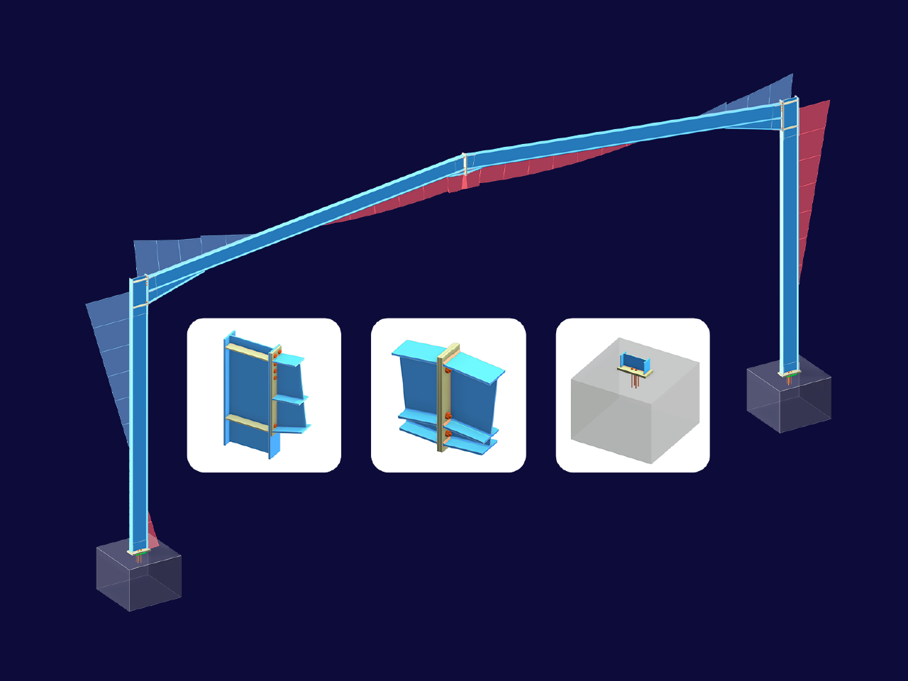
This article explores the importance of considering joint-structure interaction in modeling and design and how to do it in RFEM 6.
.png?mw=512&hash=4a84cbc5b1eacf1afb4217e8e43c5cb50ed8d827)
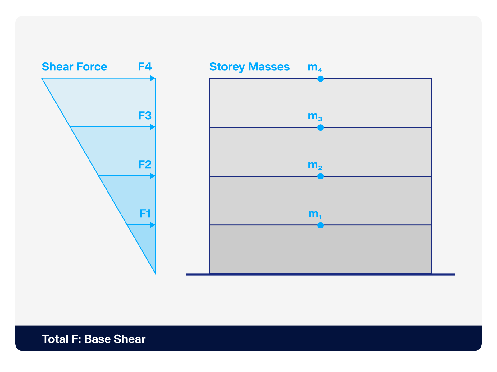
This article provides a comprehensive overview of essential seismic analysis methods, explaining their principles and applications, as well as the scenarios in which they are most effective
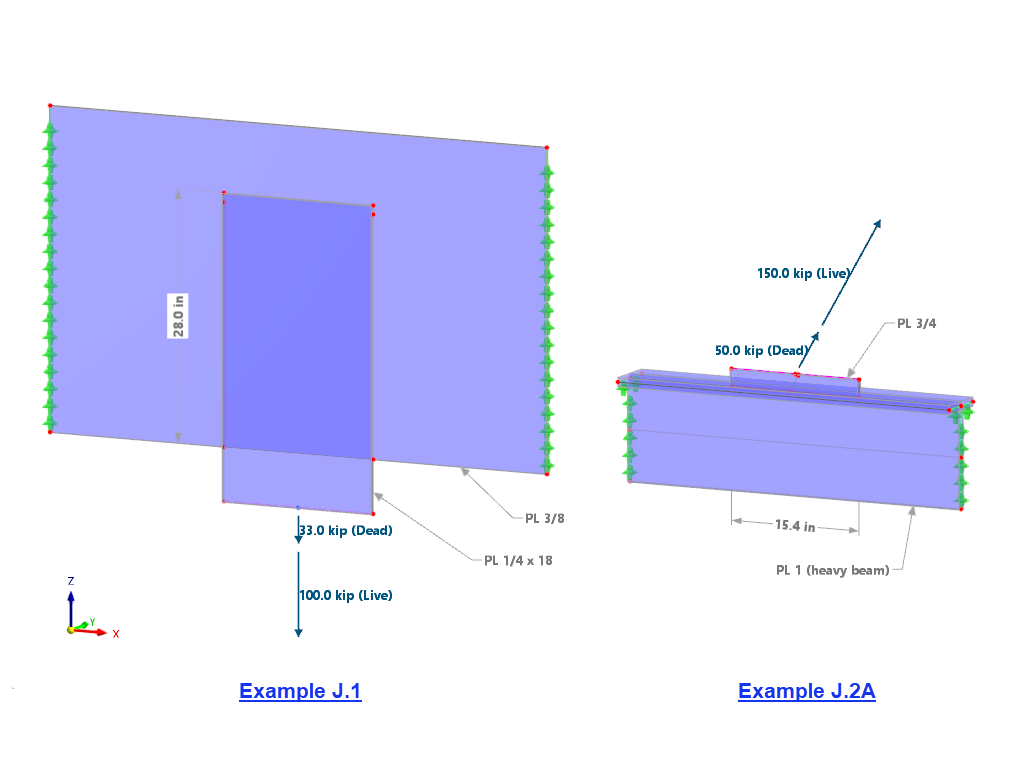
The weld stresses between surfaces can be determined using the Stress-Strain Analysis add-on in RFEM 6. Furthermore, the stress limit determined according to the applicable standard can be input to determine the stress ratio of the weld. This article focuses on the fillet weld design according to AISC 360-22 [1] with two examples from AISC Volume 1: Design Examples [2].
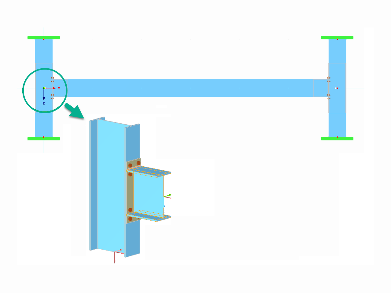
This article demonstrates how to initiate and conduct the analysis in the software, followed by a short discussion of the underlying concept.
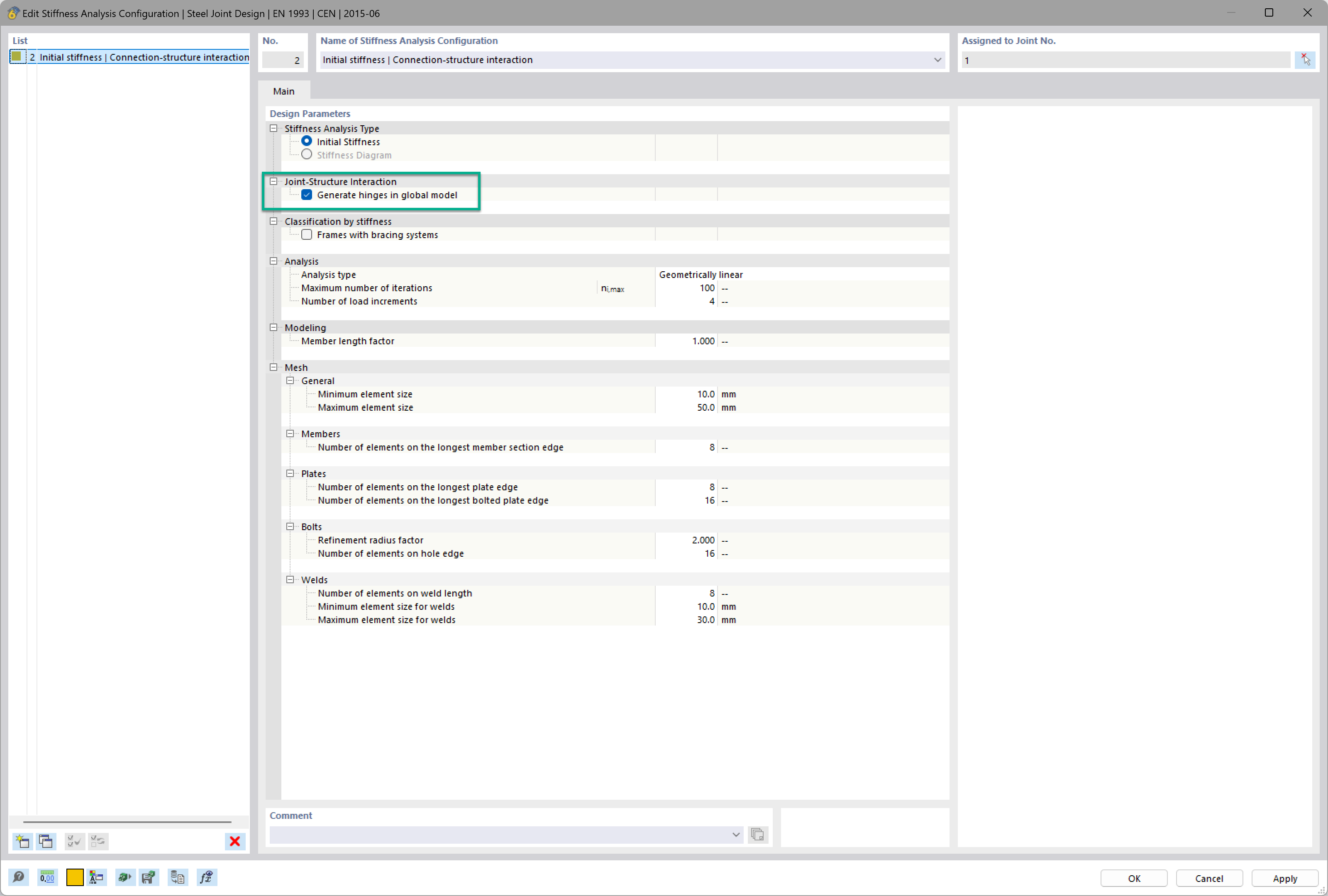
Want to automatically consider steel joint stiffness in your global RFEM model? Utilize the Steel Joints add-on!
Activate joint-structure interaction in the stiffness analysis of your steel joints. Hinges with springs are then automatically generated in the global model and included in subsequent calculations.
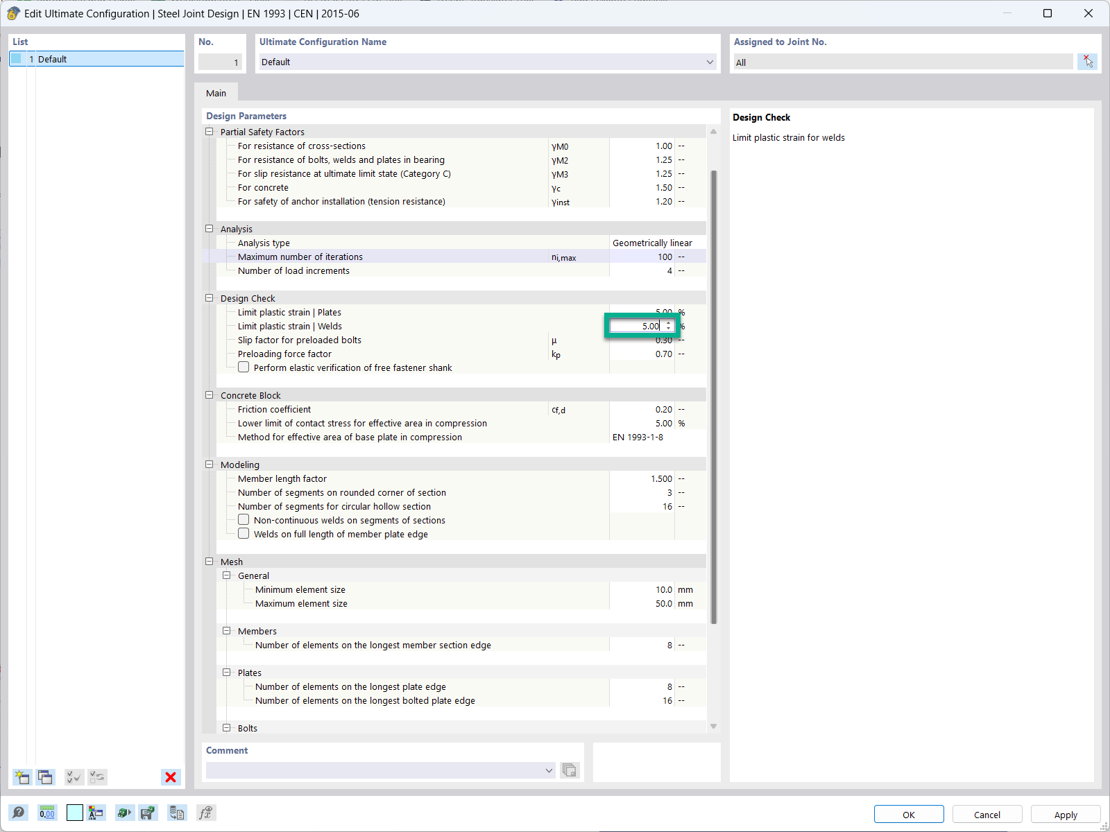
In the ultimate configuration of the steel joint design, you have the option to modify the limit plastic strain for welds.
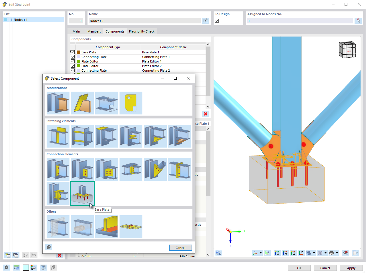
The "Base Plate" component allows you to design base plate connections with cast-in anchors. In this case, plates, welds, anchorages, and steel-concrete interaction are analyzed.
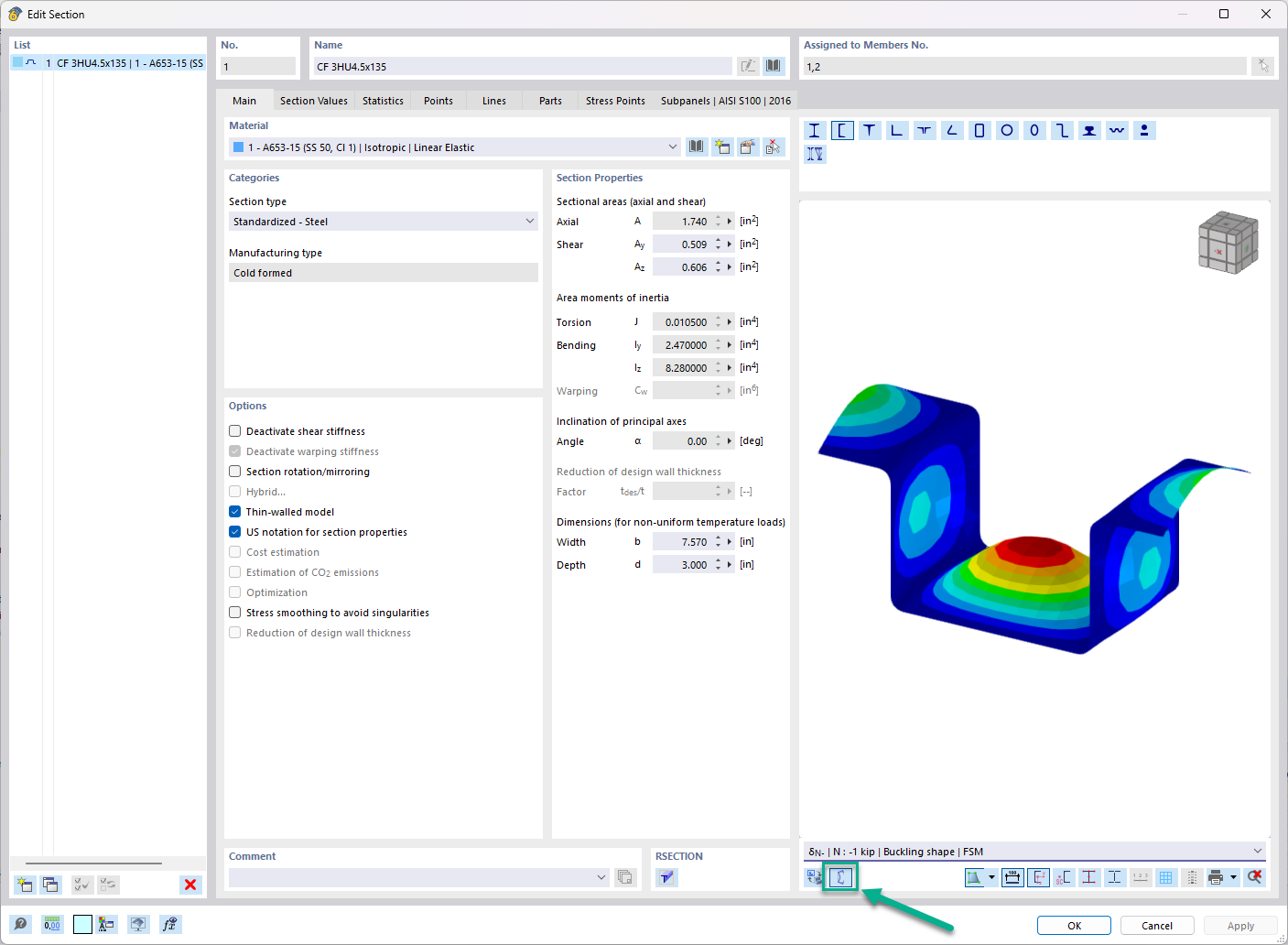
In the "Edit Section" dialog box, you can display the buckling shapes of the Finite Strip Method (FSM) as a 3D graphic.
What is the difference between SHAPE-THIN 9 and SHAPE-THIN 8?
When calculating a stiffened panel, I get the message that the boundary c/t-zone of the panel is not supported. What can I do?
When calculating a longitudinally stiffened panel, I get a message saying that the stiffener cannot be at the end of the panel. What can I do?
When calculating a buckling panel, I get a message saying that some elements are connected to the panel, but they are not defined as stiffeners. What can I do?
When selecting the elements for a stiffener of a stiffened panel, I get a message saying that at least one of the selected elements is a null element. What can I do?
During the calculation, I get a warning that some elements are connected to the buckling panel, but are not defined like stiffeners (see Image 01). What can I do?
Recommended Products for You


.png?mw=350&hash=c6c25b135ffd26af9cd48d77813d2ba5853f936c)


_1.jpg?mw=350&hash=ab2086621f4e50c8c8fb8f3c211a22bc246e0552)


.png?mw=600&hash=49b6a289915d28aa461360f7308b092631b1446e)


