

Input via parameters for one edge and symmetrical, or different parameters for each edge.
Overall
This page has 0 user ratings.
| 5 star | ||
| 4 star | ||
| 3 star | ||
| 2 star | ||
| 1 star |
SS110 | L-Shaped Plate
| Block parameters editable dynamically | |
| Number of Nodes | 6 |
| Number of Lines | 6 |
| Number of Members | 0 |
| Number of Surfaces | 1 |
| Number of Solids | 0 |
| Number of Load Cases | 1 |
| Number of Load Combinations | 0 |
| Number of Result Combinations | 0 |
| Total Weight | 3.500 tons |
| Dimensions (Metric) | 6,000 x 0,000 x 4,000 m |
| Dimensions (Imperial) | 19.69 x 0 x 13.12 feet |
You can download this structural model to use it for training purposes or for your projects. However, we do not assume any guarantee or liability for the accuracy or completeness of the model.


Duration: 01:19:08 min

Duration: 01:06:17 min

Duration: 03:03:00 min

Duration: 00:00:06 min

Duration: 02:50:31 min

Duration: 01:34:46 min

Duration: 00:01:27 min

Duration: 00:06:24 min

Duration: 04:21:12 min


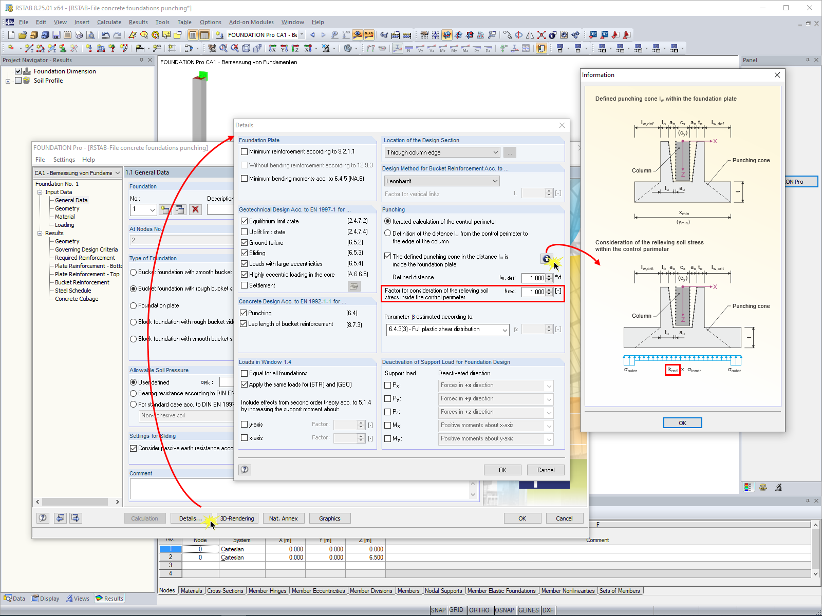
In RF-/FOUNDATION Pro, the user can freely select the proportion of the relieving soil pressure by means of the factor kred.
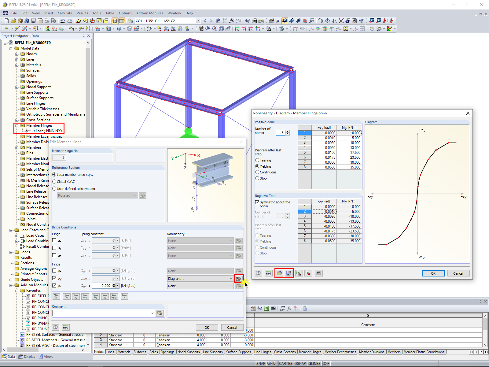
In RFEM 5 and RSTAB 8, it is possible to assign nonlinearities to member hinges. In addition to the nonlinearities "Fixed if" and "Partial activity", you can select "Diagram". If you select the "Diagram" option, you have to specify the according settings for the activity of the member hinge. For the individual definition points, it is necessary to specify the abscissa and ordinate values (deformations or rotations and the according internal forces) that define the hinge.
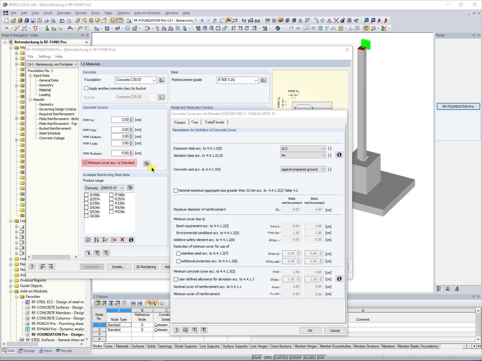
In RF-/FOUNDATION Pro, you can also consider the concrete cover for the foundation according to EN 1992-1-1.
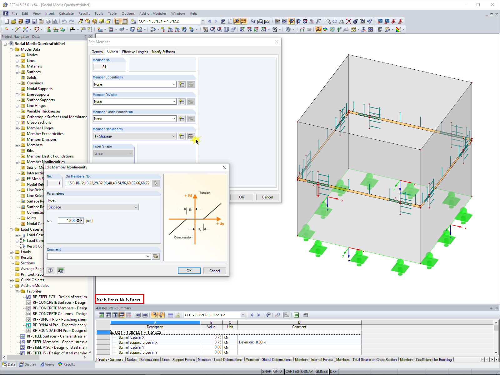
RFEM 5 allows you to use many different member nonlinearities for designing a model. In the following text, we look at an example of the use of the "slippage" member nonlinearity. The example is a simplified model of a concrete manhole with a square plan view.


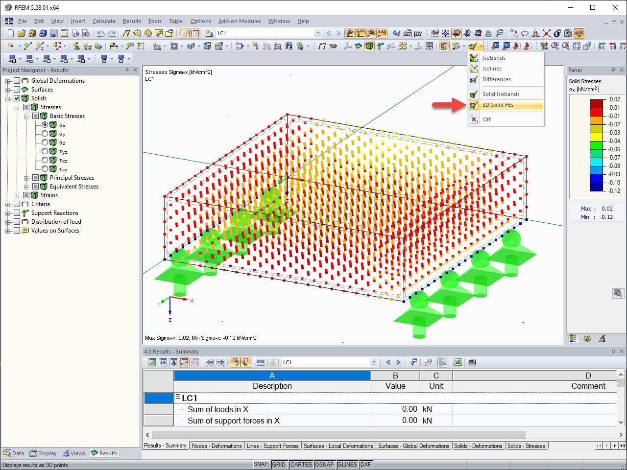
The results of solid stresses can be displayed as colored 3D points in the finite elements.
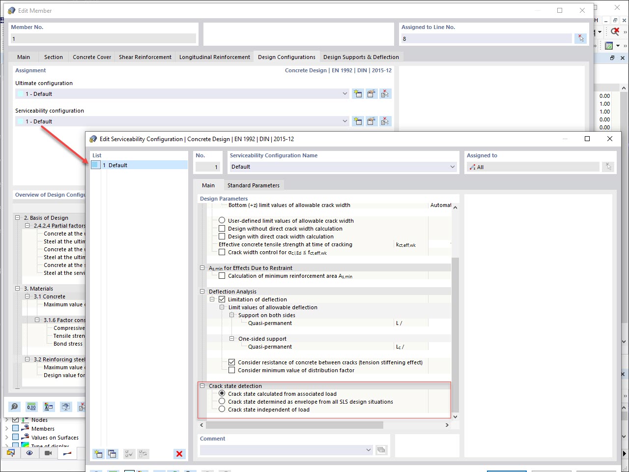
Various design parameters of the cross-sections can be adjusted in the serviceability limit state configuration. The applied cross-section condition for the deformation and crack width analysis can be controlled there.
For this, the following settings can be activated:
- Crack state calculated from associated load
- Crack state determined as an envelope from all SLS design situations
- Cracked state of cross-section - independent of load
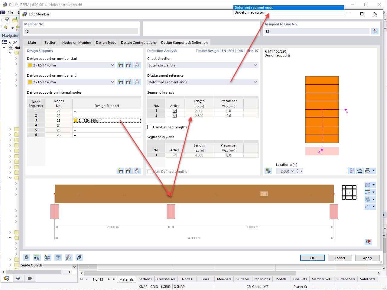
In the "Deflection and Design Support" tab under "Edit Member", the members can be clearly segmented using optimized input windows. Depending on the supports, the deformation limits for cantilever beams or single-span beams are used automatically.
By defining the design support in the corresponding direction at the member start, member end, and intermediate nodes, the program automatically recognizes the segments and segment lengths to which the allowable deformation is related. It also automatically detects whether it is a beam or a cantilever due to the defined design supports. The manual assignment, as in the previous versions (RFEM 5), is no longer necessary.
The "User-Defined Lengths" option allows you to modify the reference lengths in the table. The corresponding segment length is always used by default. If the reference length deviates from the segment length (for example, in the case of curved members), it can be adjusted.
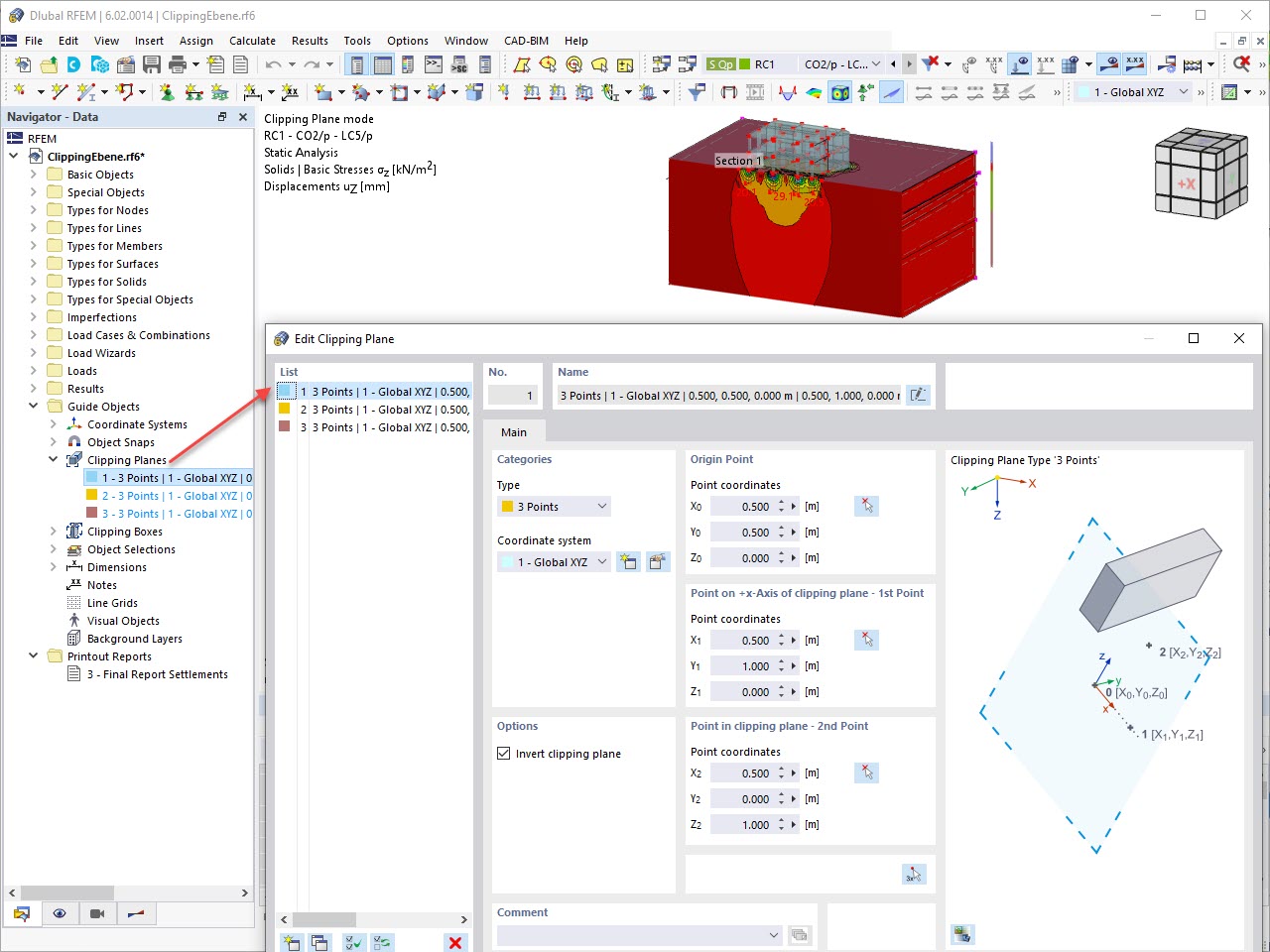
This feature also contributes to the clearly-arranged display of your results. Clipping planes are intersecting planes that you can place freely throughout the model. The zone in front of or behind the plane is consequently hidden in the display. This way, you can clearly and simply show the results in an intersection or a solid, for example.
Is it possible to quickly evaluate whether the mesh used is fine enough?
My model is unstable. What could be the reason?
Are the models and presentations from Info Day 2018 freely available, and can you send them to me?
In RF-CONCRETE Surfaces, I get a high amount of reinforcement in connection with a lever arm that is almost zero. How does such a small lever arm of internal forces come about?
When switching from the manual definition of the reinforcement areas to the automatic arrangement of the reinforcement according to window 1.4, the result of the deformation calculation changes, although the basic reinforcement has not been changed. What makes this change?
I would like to define a line support with ineffective tension and apply the tension force on this line using a nodal support instead. Why does the line support still receive a tension force?


