Analisi della trave in legno
Sarà progettata una trave di abete-larice di Douglas (Nord) di 4 pollici ⋅ 14 pollici di lunghezza nominale con un carico puntuale a metà campata di 2.500 kip. L'obiettivo di questa analisi è determinare i fattori flettenti adeguati e la capacità di flessione della trave. Si assume una durata normale del carico e dei vincoli a cerniera a ciascuna estremità dell'asta. I criteri di caricamento sono semplificati per questo esempio. Normal loading criteria can be referenced in Sec. 1.4.4 [1]. In Image 01, a diagram of the simple beam with loads and dimensions is shown.

Proprietà della trave
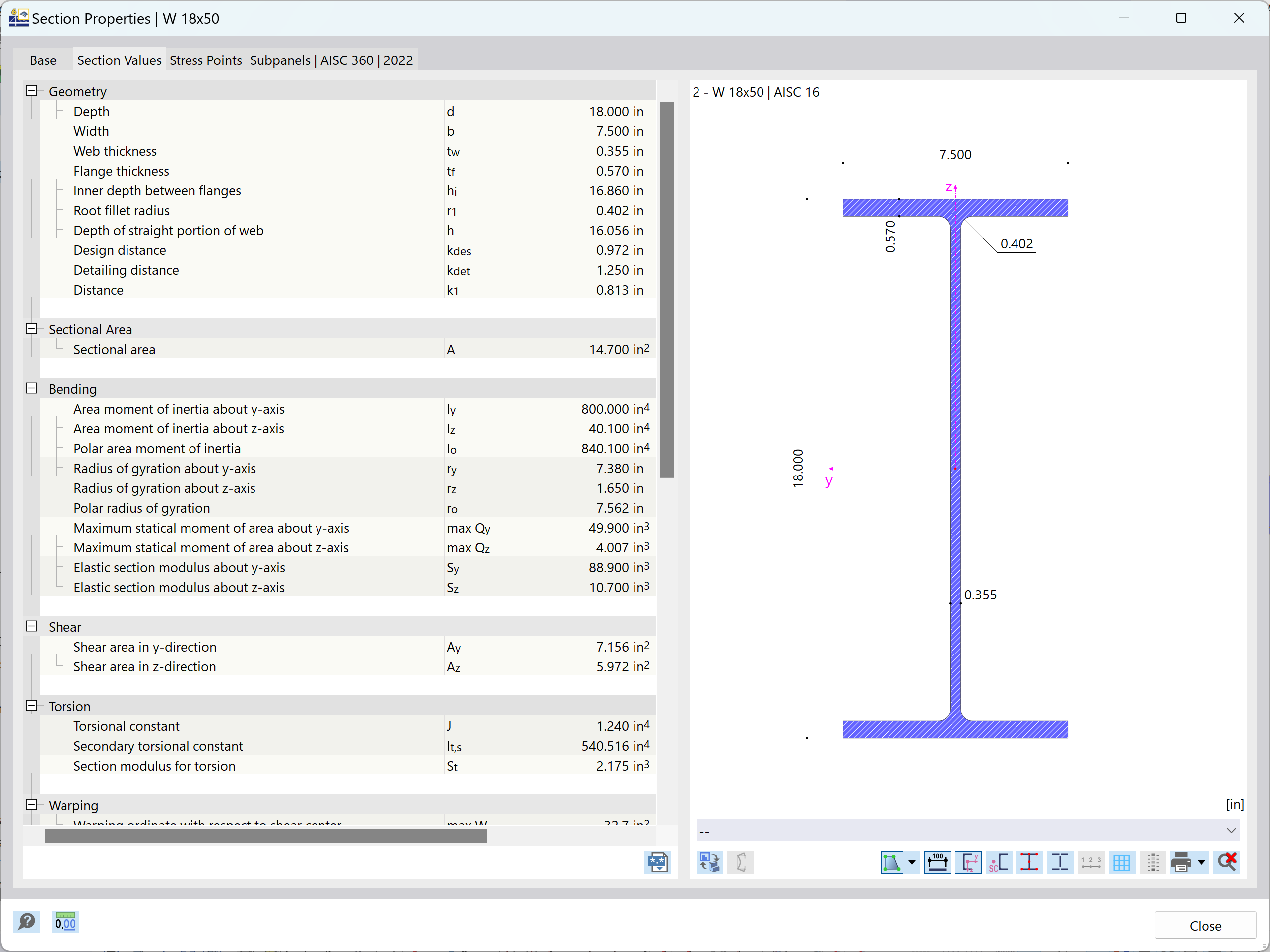
The cross-section used in this example is a 4 inch ⋅ 14 inch nominal dimension lumber. The actual cross-section property calculations of the timber beam can be viewed below:
- b = 3.50 in
- d = 13.25 in
- L = 15 ft
- Area della sezione trasversale lorda:
- Moduli di resistenza:
- Momento d'inerzia:
Il materiale che sarà utilizzato per questo esempio è abete di Douglas Fir-Larch (Nord). Le proprietà del materiale sono le seguenti:
- Valore di progetto di flessione di riferimento: Fb = 1,350 psi
- Modulo di elasticità minimo: Emin = 690,000 psi
Coefficienti di correzione della trave
For the design of timber members as per the 2018 NDS standard and the ASD method, stability factors (or adjustment factors) must be applied to the reference bending design value (Fb). Ciò fornirà il valore di progetto di flessione corretto (F'b). The factor F'b is determined with the following equation, highly dependent on the listed adjustment factors from Table 4.3.1 [1]:
Sotto, si determina ciascun coefficiente di correzione:
CD
The load duration factor is implemented to take into account different periods of loading. Neve, vento e terremoti sono considerati con CD. This factor must be multiplied by all reference design values except for the modulus of elasticity (E), modulus of elasticity for beam and column stability (Emin), and the compression forces perpendicular to the grain (Fc) based on Sec. 4.3.2 [1]. CD in this case is set to 1.00 as per Sec. 2.3.2 [1], assuming a normal load duration of 10 years.
CM
The wet service factor references design values for structural sawn lumber based on moisture service conditions specified in Sec. 4.1.4 [1]. In this case, based on Sec. 4.3.3 [1], CM is set to 1.00.
Ct
The temperature factor is controlled by a member’s sustained exposure to elevated temperatures up to 150 degrees Fahrenheit. Tutti i valori di progetto di riferimento saranno moltiplicati per il Ct. Utilizing Table 2.3.3 [1], Ct is set to 1.00 for all reference design values, assuming temperatures are lesser than or equal to 100 degrees Fahrenheit.
CF
The size factor for sawn lumber takes into account the fact that wood is not a homogeneous material. The size of the beam and type of wood are taken into account. For this example, our beam has a width between 2 inches and 4 inches and a nominal depth of 14 inches. Referencing Table 4A based on the material and size of the beam, a factor of 1.00 is applied. This info can be found in Sec. 4.3.6.1 [1].
Ci
The incising factor is used to take into account the preservative treatment wood goes through to resist decay that can cause fungal growth. Most of the time this involves pressure treatment, but in some cases it requires the wood to be incised, increasing the surface area for chemical coverage. Per questo esempio, assumeremo che il legno sia inciso. Referencing Table 4.3.8 [1], an overview of what factors each member properties must be multiplied by is shown.
r
The repetitive member factor is used in cases where multiple sawn lumber members act in a uniform fashion, leading to uniform load distributing amongst the members. These members cannot be spaced more than 24 inches from center. In questo esempio, supponiamo che la trave sia più ravvicinata e collegata da una guaina o da un rivestimento. In this case, the repetitive member factor Cr is equal to 1.15 from Sec. 4.3.9 [1].
CL
The beam stability factor checks that the torsional buckling or weak-axis buckling does not happen over long non-laterally supported spans. This is in reference to Sec. 5.3.4 [1] and will be calculated below.
Cfu
The flat use factor is used when the loading of a timber member is applied to the weak axis versus the strong axis. For this example, we will be applying the loading to the strong axis, so this factor will not be included in our calculations.
CT
The buckling stiffness factor is used to take into account plywood sheathing that can increase the buckling resistance of compression truss chords. For this example, we will be assuming there is no plywood sheathing, so CT is equal to 1.00.
Modulo di elasticità rettificato
Anche il modulo di riferimento dei valori di elasticità (E ed Emin) deve essere modificato. The adjusted modulus of elasticity (E' and E'min) are determined from Table 4.3.1 [1] and the incising factor Ci is equal to 0.95 from Table 4.3.8 [1].
Coefficiente di stabilità della trave (CL)
The beam stability factor (CL) is needed in order to calculate the beam's adjusted bending design value and further, to calculate the bending design ratio. Le seguenti operazioni includeranno le equazioni ed i valori necessari per trovare CL.
The effective length of this beam can be calculated using the lateral unsupported length (lu), which is the full length of the beam. The member length converted into inches is used in the effective length equation from Table 3.3.3 [1].
Next, we will calculate the slenderness ratio of bending members (RB) utilizing Sec. 3.3.3.6 [1] with the beam width, depth, and effective span length.
Now, the critical buckling design value for bending members (Fbe) is calculated with reference to Sec. 3.3.3.8 [1]. Si utilizza il modulo di elasticità per stabilità della trave (E'min) insieme al precedentemente calcolato rapporto di snellezza di flessione (RB).
Il coefficiente di stabilità della trave (CL) può essere calcolato con riferimento alla stessa sezione in alto.
The incising factor Ci is equal to 0.80 for Fb from Table 4.3.8 [1]. Now, all adjustment factors have been determined from Table 4.3.1 [1]. Pertanto, si può calcolare il valore di progetto di flessione adattato (F'b).
Rapporto di progetto della trave
L'obiettivo finale di questo esempio è ottenere il rapporto di progetto per questa trave semplice. This will determine if the member size is adequate under the given load, or if it should be further optimized. Calculating the design ratio requires the maximum bending moment and actual bending stress.
The maximum moment about the x-axis (Mmax) is found by the following.
Next, the actual bending stress (fb) is calculated by plugging in Mmax and S from previous calculations. This can be seen below, utilizing Sec. 3.3.2.1 [1].
Finally, the design ratio (η) as per Sec. 3.3.1 ora può essere calcolato.
Applicazione in RFEM
For timber design as per the 2018 NDS standard in RFEM, the add-on module RF-TIMBER AWC analyzes and optimizes cross-sections based on loading criteria and member capacity for a single member or set of members. Questo è disponibile per i metodi di verifica LRFD o ASD. Quando si modella e si progetta la trave dell'esempio in RF-TIMBER AWC, i risultati possono essere confrontati.

Nella tabella Dati generali del modulo aggiuntivo RF-TIMBER AWC, sono selezionati l'asta, le condizioni di carico e i metodi di progetto. The material and cross-sections are defined from RFEM and the load duration is set to ten years. The moisture service condition is set to Dry and the temperature is equal to or less than 100 degrees Fahrenheit. Lateral-Torsional Buckling is defined as according to Table 3.3.3 [1]. The module calculations produce an actual bending stress (fb) of 1,098.50 psi and an adjusted bending design value (f'b) of 1,189.59 psi. A design ratio (η) of 0.92 is determined from these values aligning well with the analytical hand calculations shown above.


..png?mw=320&hash=bd2e7071b02d74aef6228d22c4b83867d2d7e1a5)


.png?mw=600&hash=49b6a289915d28aa461360f7308b092631b1446e)