You can use zones to subdivide the model into parts and assign specific properties, such as materials with their roughness parameters. The zones are also useful when you want to examine the local surface results of components, inclusive of their drag forces.
To manage the zones, select the "Zones" tab in the work window. The "Editor" panel is automatically set to manage zones. When you have imported the model from RFEM 6 / RSTAB 9, the materials defined in the Dlubal application are preset in the "Zones" section of the panel.
The triangular mesh elements are displayed on the model. You can assign elements to the preset zones. If you want to define a new zone, click
![]() in the "Edit Zones" section of the panel.
in the "Edit Zones" section of the panel.
Zones can be automatically generated based on surface numbers from RFEM, you can find the option in the menu "Edit" -> "Zones" -> "Generate zones from surface numbers".
Materials
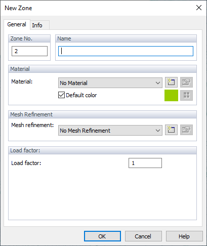
In the "New Zone" dialog box, enter the "Name" of the zone. You can select one of the existing materials from the list. The
![]() button allows you to define a new material.
button allows you to define a new material.
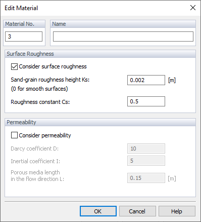
In "Edit Material", you can set the roughness of the material or, in RWIND 2 Pro, new permeability on the zone; more information about these parameters can be found in Chapters Materials and Pemeable Surfaces. If you do not change the preset "No Material" option, the global roughness parameters will be applied to the new zone.
Mesh Refinements
In this section, you can set mesh refinements, which can then be assigned to zones. More information can be found in Chapter Mesh Refinements.
Load Factor
In the next section, you can define the "Load Factor" parameter for the zone. The load factor is a post-processing factor, by which the resulting load is multiplied, the image below shows the results after applying the load factor to the windscreen of the model car.
Selection Tools
To allocate mesh elements to a zone, use one of the options in the "Selection Tools" section of the panel. You can either select the triangle element(s) first, and then click on the zone in the panel, or select the zone first and then assign the triangle(s).
The "Selection Tools" buttons have the following functions:
|
|
Selects a single triangle element when clicking it with a pointer or select an area for volume selection. |
|
|
Selects several elements when moving brush over them. |
|
|
The volume selection tool. It selects several elements when drawing a rhomboid over them. |
|
|
The volume selection tool. It selects several elements when drawing a circle from a selected center. |
|
|
The volume selection tool. It selects several elements when defining a free polygon around them. |


