


Historia del Usuario
En el primer ejemplo, procedemos con un diseño preliminar, enfocándonos particularmente en calcular la fuerza total. Se selecciona como un plano cuadrado 2D. Pertenece al Grupo 1 del Boletín WTG-Merkblatt-M3:
- G1: Valores cualitativos con requisitos de baja precisión para su uso en la investigación básica o diseño preliminar. El esfuerzo y los requisitos para el nivel de detalle se reducen, ya que a menudo no se aclaran completamente todas las condiciones de contorno.
- R1: Solitario (sin edificios circundantes), análisis de direcciones de viento individuales importantes.
- Z1: Valores medios estadísticos, siempre y cuando se trate de procesos de flujo estacionarios donde las fluctuaciones (p. ej., debido a la turbulencia del flujo entrante) puedan capturarse suficientemente por otras medidas.
- S1: Efectos estáticos. Es suficiente representar el modelo estructural con el detalle mecánico necesario, pero sin propiedades de masa y amortiguación.
Las dimensiones del ejemplo se muestran en la Figura 1, y el supuesto de entrada se ilustra en la Tabla 1:
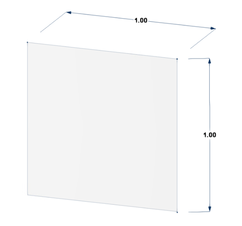
Tabla 1: Datos de Entrada del Ejemplo de Verificación del Plano Cuadrado 2D
| Modelo | Plano cuadrado 2D |
|---|---|
| Dimensión | a = 1 m |
| Velocidad básica del viento | V = 30 m/s |
| Densidad del aire | ρ = 1.225 kg/m³ |
| Solucionador | Basado en presión |
| Modelo de turbulencia | Steady k-ω SST |
| Categoría de terreno | 2 |
| Tipo de perfil de velocidad del viento en RFEM | Máximo |
| Algoritmo numérico | Algoritmo SIMPLE |
| Discretización | Segundo orden |
| Presión residual | 10⁻⁴ |
| Viscosidad cinemática | ν = 1.5 × 10⁻⁵ |
En este ejemplo, compararemos los valores de fuerza del viento entre EN 1991-1-4 y RWIND. La fórmula de la fuerza del viento en la Sección 5.3 del Eurocódigo se define:
|
cscd |
Structural factor |
|
cf |
Force coefficient for the structure or structural element |
|
qp(ze ) |
Peak velocity pressure at reference height ze |
|
Aref |
Reference area of the structure or structural element |
Los coeficientes de fuerza (d=b=1 → Cf,0=2.10) de las secciones rectangulares con esquinas afiladas y sin flujo en el extremo libre se pueden obtener en la Figura 7.23 en EN 1991-1-4, y el factor de reducción (ψr) para una sección transversal cuadrada con esquinas redondeadas (r/b=0 → ψ r=1) se puede obtener de la Figura 7.24 en EN 1991-1-4. Los valores indicativos del factor de efecto final ψλ=0.63 como función del coeficiente de solidez φ=1 contra esbeltez λ=2 se pueden obtener en la Figura 7.36 en EN 1991-1-4.
El coeficiente de fuerza cf de los elementos estructurales de la sección rectangular con el viento soplando normalmente sobre una superficie plana debe determinarse mediante la Expresión (7.9) en EN 1991-1-4:
|
cf,0 |
The force coefficient of rectangular sections with sharp corners and without free-end flow |
|
ψr |
The reduction factor for square sections with rounded corners |
|
ψλ |
The end-effect factor for elements with free-end flow |
- Velocidad media del viento
La velocidad media del viento vm (ze) a la altura de referencia z_e depende de la rugosidad del terreno, la orografía del terreno y la velocidad básica del viento vb. Se determina utilizando la ecuación (4.3) de EN1991-1-4:
- Turbulencia del viento
La intensidad de turbulencia Iv (ze) a la altura de referencia ze se define como la desviación estándar de la turbulencia dividida por la velocidad media del viento. Se calcula de acuerdo con la Ecuación 4.7 de EN1991-1-4. Para el caso examinado ze menor que zmin:
- Presión de velocidad básica
La presión de velocidad básica q_b es la presión correspondiente al momento del viento determinado en la velocidad básica del viento vb. La presión de velocidad básica se calcula de acuerdo con la relación fundamental especificada en EN1991 -14 §4.5(1):
donde ρ es la densidad del aire de acuerdo con EN1991-1-4 §4.5(1). En este cálculo, se considera el valor ρ=1.225 kg/m3.
- Presión de velocidad pico
La presión de velocidad pico qp (ze) a la altura de referencia ze incluye fluctuaciones de velocidad media y a corto plazo. Se determina de acuerdo con la Ecuación 4.8 de EN1991-1-4:
Entonces, la fuerza del viento se puede calcular:
La Imagen 2 muestra un estudio de sensibilidad de malla en RWIND para la placa 2D. A medida que la densidad de la malla aumenta del 10% al 40%, el coeficiente de fuerza Cf disminuye y se estabiliza en 1.23 a partir del 30%, lo que indica resultados independientes de la malla y asegura la precisión de la simulación sin refinamiento innecesario.

Además, el estudio de malla computacional debe realizarse de acuerdo con el siguiente enlace:
El Hit Rate Método del WTG-Merkblatt M3 proporciona dos métodos clave para validar los resultados de simulación. Evalúa cuántos de los valores simulados Pi coinciden correctamente con los valores de referencia Oi dentro de una tolerancia definida, utilizando un enfoque de clasificación binaria (acierto o error). Este enfoque evalúa la fiabilidad de la simulación calculando una tasa de aciertos q, similar a las funciones de confianza utilizadas en la teoría de la fiabilidad. En contraste, el método del Error Cuadrático Medio Normalizado (e2) ofrece una evaluación de precisión más detallada al cuantificar la desviación cuadrática media entre los valores simulados y de referencia, normalizada para tener en cuenta las diferencias de escala. Juntos, estos métodos proporcionan medidas tanto cualitativas como cuantitativas para la validación de simulaciones.
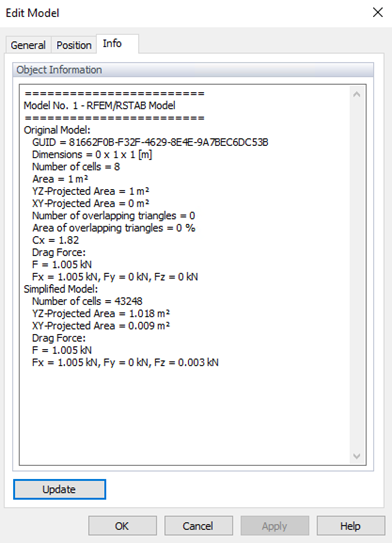
Resultados en RWIND y Comparación con Eurocódigo
En RWIND, los resultados de las fuerzas totales (en las Figuras 3 y 4) están disponibles en la pestaña Info del modelo Editar. La diferencia entre RWIND y el Eurocódigo es de aproximadamente Wrel = 2.45% (menos que los criterios mencionados en WTG); entonces la tasa de aciertos se puede obtener como q=100%, lo que muestra un buen acuerdo. El error cuadrático medio normalizado bajo e2=0.0005 confirma un fuerte acuerdo entre la simulación y las mediciones, cumpliendo efectivamente con los estándares de validación.

Aquí está el modelo 3D de la placa 2D:
