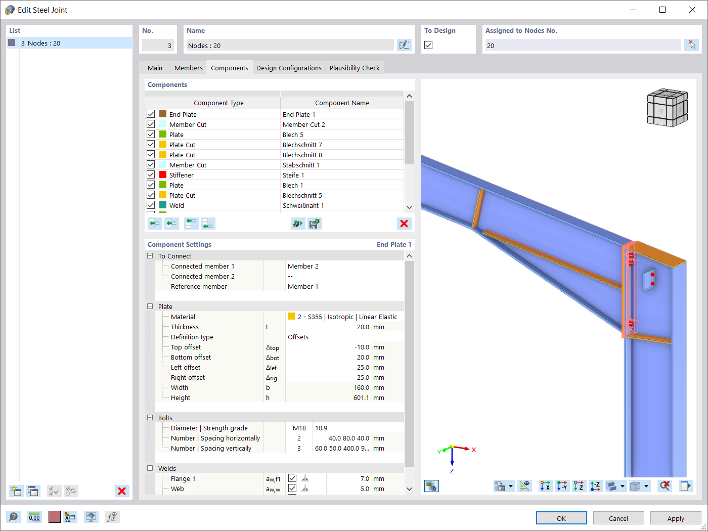
We illustrate it with the following example of an end plate connection of the continuous column with the beam.

The rotational stiffness for moment about the y-axis is set to be calculated, and we obtained following results:
SMy+ = SMy- = 21.5 MNm/rad
The initial stiffness for positive and negative moments is the same in this example because the joint geometry is symmetric about the y-axis. If it were not, the results would be different.
But how we obtained the number 21.5 MNm/rad?
The initial stiffness is calculated using FEA analysis, where two submodels are modeled:
- Surface submodel: This submodel is the same as the one used for stress-strain analysis. It is supported at all member ends by rigid supports and loaded by a unit force at the chosen end of the member for stiffness analysis. Both negative and positive loading are considered in two different load cases. The nodal support on the verified member is deactivated in these load cases using a Structure Modification object.
- Member submodel: This submodel is constructed using analogous members to the surface submodel, and the connections between them are rigid. The purpose of this submodel is to correct the deformation caused by the member deformation effect.

OK, I have these two submodels calculated. But how to derive the initial stiffness from the results?
In our example we want to calculate rotational stiffness of the beam. So, we concentrate on rotation φy at the end of the beam.

Then we make the correction:
φy (final) = φy (surface submodel) - φy (member submodel) = 0.016768 - 0.004497 = 0.012271 mrad
When we have the final rotation φy, then we can calculate the initial stiffness:
SMy = My / φy (final) = 0.000264 MNm / 0.000012271 rad = 21.5 MNm/rad
So that is the whole science. Similarly, it works for rotational stiffness in the second direction and for axial stiffness.
There are some important notes to consider when using this function:
- The initial stiffness is determined based on a member model with rigid contacts. If additional plates, such as stiffeners or haunches, are added to the model, the surface submodel may become stiffer than the member submodel, resulting in an infinite stiffness (S = ∞). This may seem unusual but it is correct. From a global member model perspective, a such a rigid connection would still be modeled as a rigid contact between members. Sometimes, even a seemingly less rigid joint can have a higher stiffness than expected. However, it is crucial to understand the implications for the global member model. If a rigid contact is placed in less rigid conditions, a higher stiffness may not have significant meaning for the global member model.
- With the future development of the submodel (independent mesh, member end detail improvement or improvements of bolt and weld detailing) the initial stiffness results can change apparently a lot. However, it do not have to mean so much for the use of stiffness in the model. So it is very important to access these future changes with all the context. Before automatic joint-model integration, we plan to implement classification of the joint acc. to its initial stiffness (rigid, semi-rigid and pinned). This should help with orientation in the results.
And here is an example at the end. In the picture below, you can see six examples of connections with different stiffness, along with a comparison to fully rigid and fully pinned connections in the member model. Currently, all examples are referred to as semi-rigid, but once the classification is complete, some of them will likely be classified as either rigid or pinned. The hinges in the global member model should be then set accordingly, taking this classification into consideration.


.jpg?mw=350&hash=91f398b559b26a6ac36fd7ecdf5e395e7b9b856d)


.png?mw=600&hash=49b6a289915d28aa461360f7308b092631b1446e)

