In this tutorial, we would like to inform you about the essential features of the RFEM program. In the first part, a model was defined and a structural analysis was carried out. After performing the concrete design in the second part, the third part now deals with the design of steel members. AISC 360-22 is used as a standard.
Online Manuals
RFEM 6 | Tutorial - Steel Design (USA)
RFEM 6 | Tutorial - Steel Design (USA)


Duration: 01:10:25 min

Duration: 01:05:10 min

Duration: 00:52:56 min

Duration: 01:08:12 min

Duration: 00:58:00 min
Duration: 01:02:00 min
Duration: 01:01:43 min

Duration: 00:00:35 min
Duration: 01:06:48 min


In this article, we will explore the various types of stability failures, delving into their key features, causes, and how they manifest in different structural systems.

According to AISC Design Guide 9 Section 4.1 [1], the following torsional stresses must be considered for open cross-sections subjected to warping:

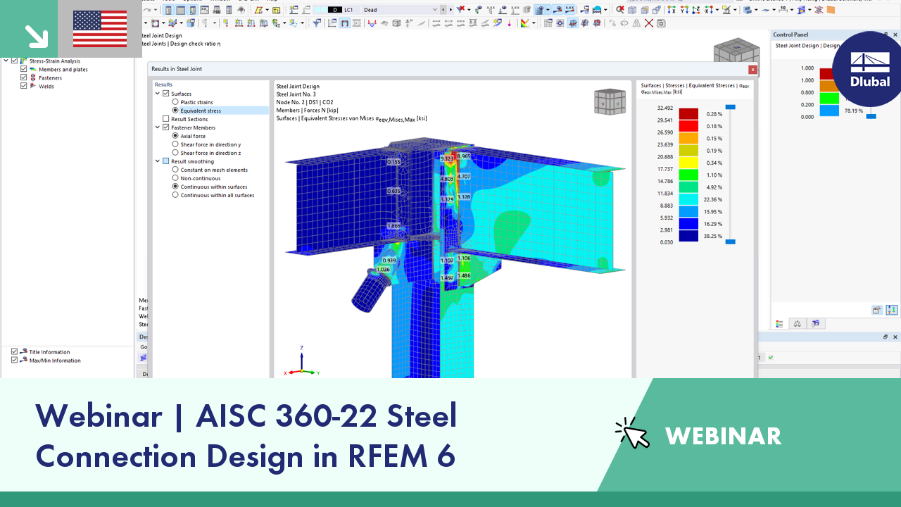
This article will show you how to model stiffened tubular joints in the Steel Joints Add-on.

Utilizing the Steel Design Add-on, steel design is possible according to the AISC 360-22 standard. The following article will compare the result output when calculating lateral torsional buckling according to Chapter F vs. an Eigenvalue Analysis.


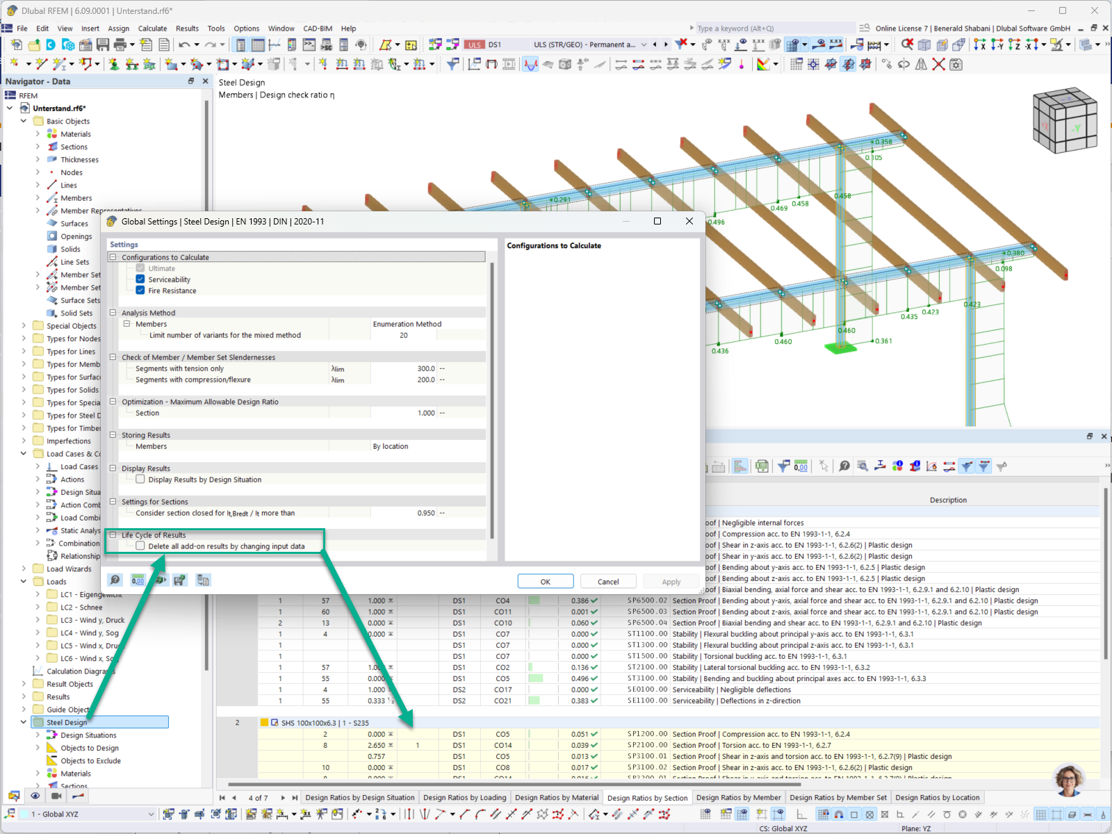
It is now possible to keep the results of the steel, steel joint, aluminum, and timber design despite changing the design properties and settings (see the setting in the image). The results are thus not deleted, but marked as invalid.
When restarting the design, only the invalid design results are updated. If objects are subsequently added to the design, they are additionally designed when restarting the design, while the previously calculated results remain valid.

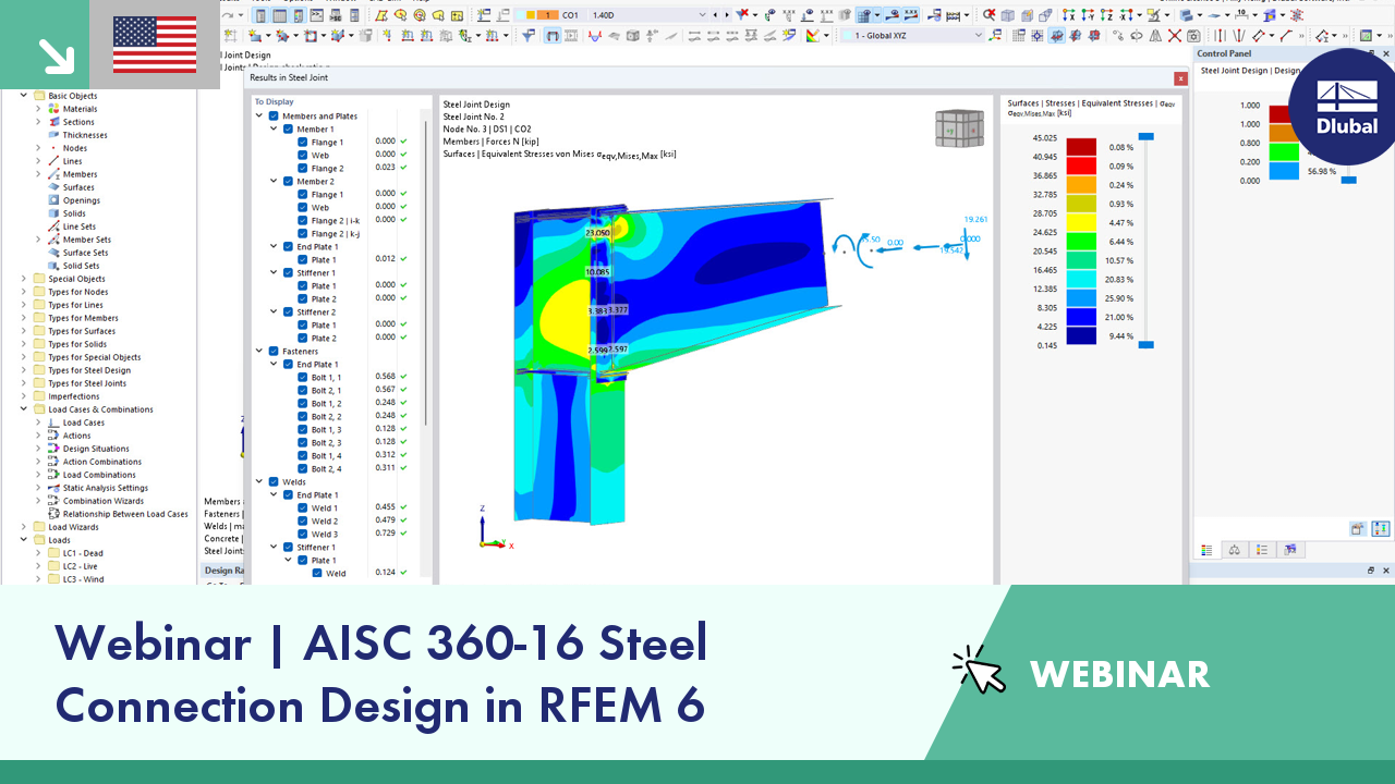
The seismic design result is categorized into two sections: member requirements and connection requirements.
The "Seismic Requirements" include the Required Flexural Strength and the Required Shear Strength of the beam-to-column connection for moment frames. They are listed in the ‘Moment Frame Connection by Member’ tab. For braced frames, the Required Connection Tensile Strength and the Required Connection Compressive Strength of the brace are listed in the ‘Brace Connection by Member’ tab.
The program provides the performed design checks in tables. The design check details clearly display the formulas and references to the standard.
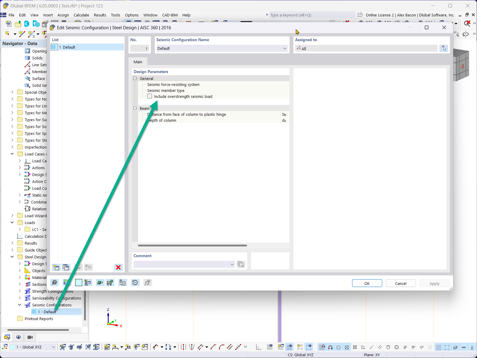
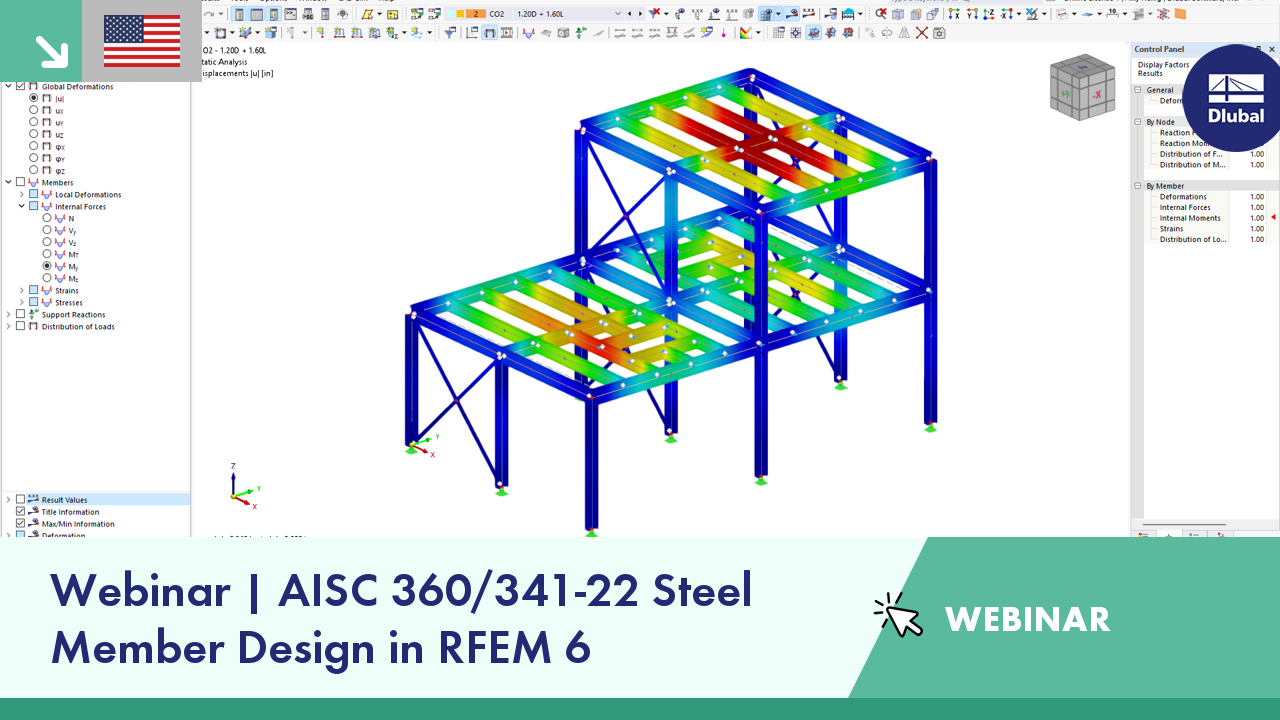
In the Steel Design add-on, you can perform the seismic design of steel members according to AISC 341‑16.
Five SFRS types (Seismic Force-Resisting Systems) are available for this.

In the Steel Design add-on, you can perform the stability and cross-section design checks of cold-formed sections according to EN 1993‑1‑3 in compliance with Sections 6.1.2 – 6.1.5 and 6.1.8 – 6.1.10.
Go to Explanatory Video
I am using the Steel Design add-on. Can I define the cross-section class manually?
The lateral torsional buckling (LTB) check looks missing in the Steel Design. What could be the reason?
How can I perform member design by case for different settings in the design configuration?
How can I design single-angle compression member according to AISC Section E5?
Is it possible to use the General Method according to EN 1993‑1‑1, 6.3.4 to design structural components with an asymmetric cross-section in the Steel Design add-on for RFEM 6 or RSTAB 9?
Can I use design cases in RFEM 6 in the same way as in RFEM 5?


.png?mw=350&hash=e70d8df86e6471bb10defcbc6d5854915810a94c)


