- Automatic import of internal forces from RFEM
- Ultimate limit state and serviceability limit state design
- The module extension EC2 for RFEM enables the design of reinforced concrete members according to EN 1992‑1‑1:2004 (Eurocode 2) and the following National Annexes:
-
 DIN EN 1992-1-1/NA/A1:2015-12 (Germany)
-
 ÖNORM B 1992-1-1:2018-01 (Austria)
-
 NBN EN 1992-1-1 ANB:2010 (Belgium)
-
 BDS EN 1992-1-1:2005/NA:2011 (Bulgaria)
-
 EN 1992-1-1 DK NA:2013 (Denmark)
-
 NF EN 1992-1-1/NA:2016-03 (France)
-
 SFS EN 1992-1-1/NA:2007-10 (Finland)
-
 UNI EN 1992-1-1/NA:2007-07 (Italy)
-
 LVS EN 1992-1-1:2005/NA:2014 (Latvia)
-
 LST EN 1992-1-1:2005/NA:2011 (Lithuania)
-
 MS EN 1992-1-1:2010 (Malaysia)
-
 NEN-EN 1992-1-1+C2:2011/NB:2016 (Netherlands)
-
 NS EN 1992-1 -1:2004-NA:2008 (Norway)
-
 PN EN 1992-1-1/NA:2010 (Poland)
-
 NP EN 1992-1-1/NA:2010-02 (Portugal)
-
 SR EN 1992-1-1:2004/NA:2008 (Romania)
-
 SS EN 1992-1-1/NA:2008 (Sweden)
-
 SS EN 1992-1-1/NA:2008-06 (Singapore)
-
 STN EN 1992-1-1/NA:2008-06 (Slovakia)
-
 SIST EN 1992-1-1:2005/A101:2006 (Slovenia)
-
 UNE EN 1992-1-1/NA:2013 (Spain)
-
 CSN EN 1992-1-1/NA:2016-05 (Czech Republic)
-
 BS EN 1992-1-1:2004/NA:2005 (United Kingdom)
-
 TKP EN 1992-1-1:2009 (Belarus)
-
 CYS EN 1992-1-1:2004/NA:2009 (Cyprus)
-
- In addition to the National Annexes (NA) listed above, you can also define a specific NA, applying user‑defined limit values and parameters.
- Flexibility due to detailed setting options for basis and extent of calculations
- Fast and clear results output for an immediate overview of the result distribution after the design
- Graphical results output integrated in RFEM; for example, required reinforcement
- Numerical results clearly arranged in tables and graphical display of the results in the model
- Complete integration of results in the RFEM printout report
RF-CONCRETE| Features


Duration: 00:02:24 min

Duration: 00:00:09 min

Duration: 00:00:41 min

Duration: 01:03:28 min

Duration: 00:54:02 min

Duration: 01:05:46 min

Duration: 00:01:02 min

Duration: 00:59:31 min
Duration: 00:00:48 min


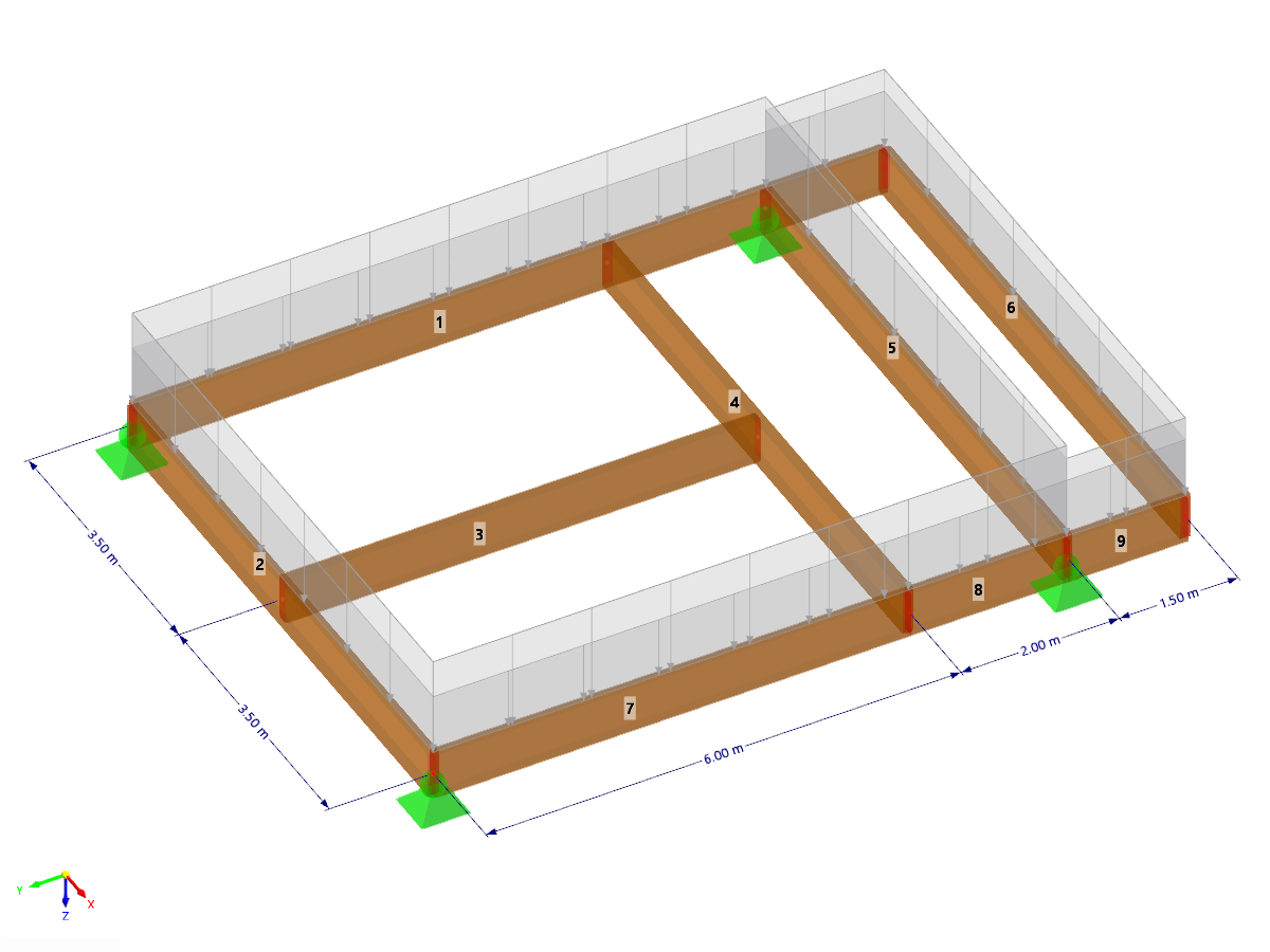
For the serviceability of a structure, the deformations must not exceed certain limit values. This article describes an example that shows how to analyze the deflection of members using Dlubal's design add-ons.
Lateral-Torsional Buckling (LTB) is a phenomenon that occurs when a beam or structural member is subjected to bending and the compression flange is not sufficiently supported laterally. This leads to a combination of lateral displacement and twisting. It is a critical consideration in the design of structural elements, especially in slender beams and girders.

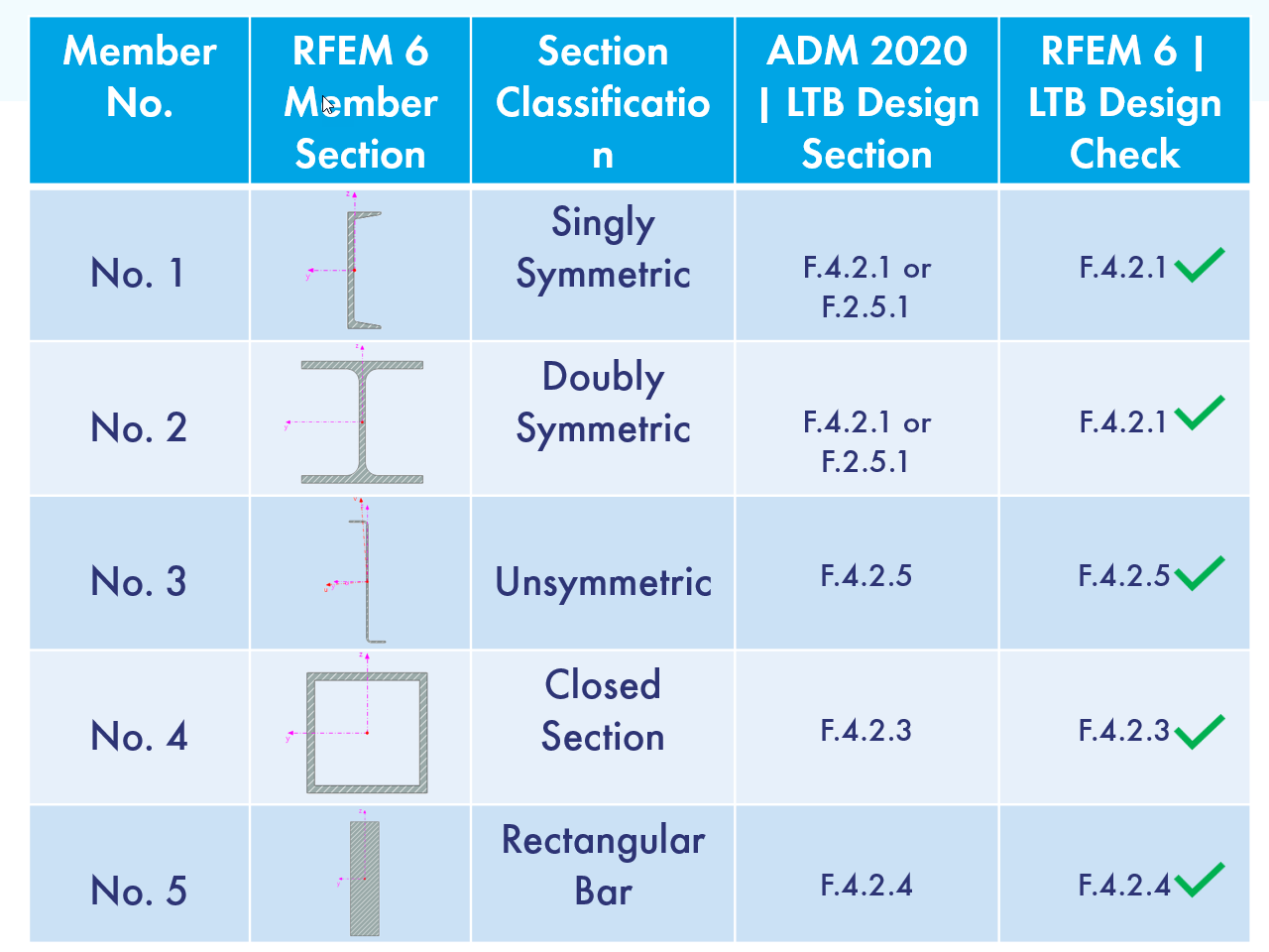
RFEM 6 offers the Aluminum Design add-on for the design of aluminum members. This article shows how Class 4 sections are designed according to Eurocode 9 in the program.
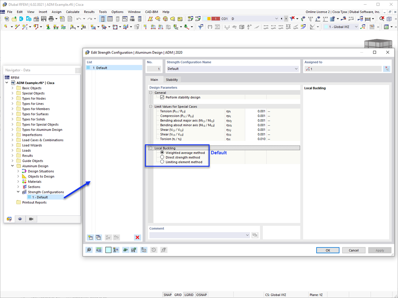
This article discusses the options available for determining the nominal flexural strength, Mnlb for the limit state of local buckling when designing according to the 2020 Aluminum Design Manual.


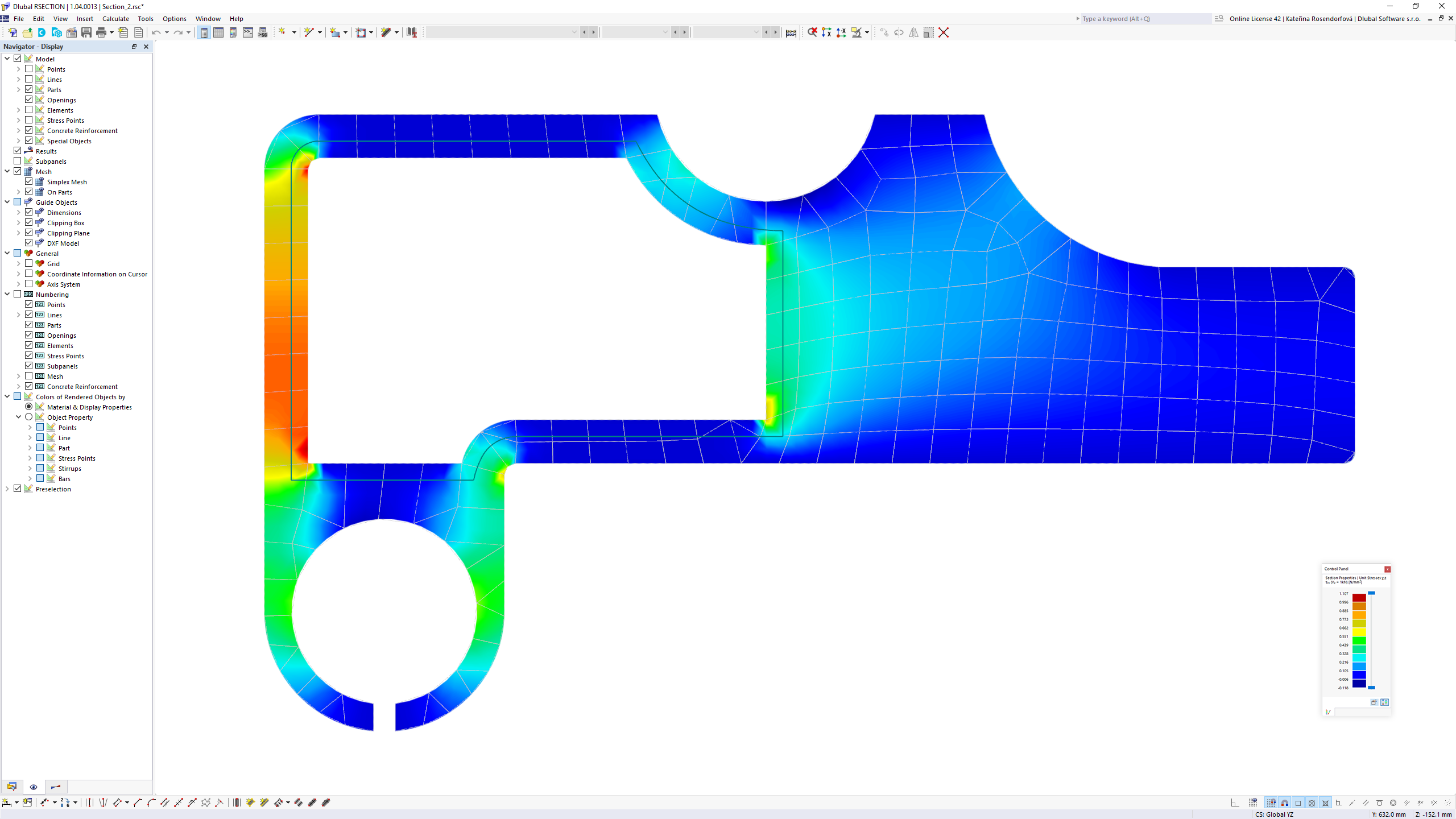
The Aluminum Design add-on provides you with further options. Here you can also design general cross-sections that are not predefined in the cross-section library. For example, create a cross-section in the RSECTION program and then import it into RFEM/RSTAB. Depending on the design standard used, you can select from various design formats. This includes, for example, the equivalent stress analysis.
With a license for RSECTION and "Effective Sections", you can also perform the design checks while taking into account the effective cross-section properties according to EN 1993‑1‑5.
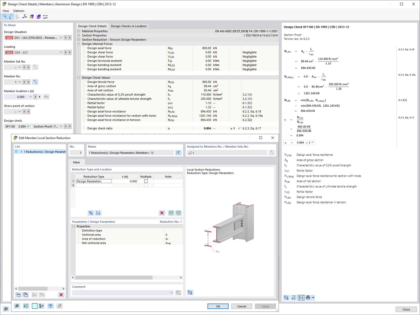
You know for sure that when connecting tension-loaded components with bolted connections, you need to consider the cross-section reduction due to the bolt holes in the ultimate limit state design. The structural analysis programs also have a solution for this. In the Aluminum Design add-on, you can enter a member local section reduction for this. Enter the reduction of the cross-section as an absolute value or as a percentage of the total area at all relevant locations.

- Calculation of deflections and comparison with the normative or manually adjusted limit values
- Consideration of a precamber for the deflection analysis
- Different limit values are possible, depending on the design situation type
- Manual Adjustment of Reference Lengths and Segmentation by Direction
- Calculation of deflections related to the initial structure or to the deformed structure
- Further detailed design checks depending on the selected design standard (for example, vibration design according to EN 1999‑1‑1, 7.2.3)
- Graphical result display integrated in RFEM/RSTAB; for example, the design ratio of a limit value, or the deformation or the sag
- Complete integration of the results into the RFEM/RSTAB printout report

The program does a lot of work for you. For example, the load or result combinations required for the serviceability limit state are generated and calculated in RFEM/RSTAB. You can select these design situations for the deflection analysis in the Aluminum Design add-on. Depending on the specified precamber and reference system, the program determines the deformation values at each location of a member. They are then compared to the limit values.
You can specify the deformation limit value individually for each structural component in Serviceability Configuration. In this case, you define the maximum deformation depending on the reference length as the allowable limit value. By defining design supports, you can segment the components. In this way, you can determine the corresponding reference length automatically for each design direction.
And that's not all. Based on the position of the assigned design supports, the program allows you to automatically determine the distinction between beams and cantilevers. The limit value is thus determined accordingly.
I would like to analyze temporary structures. Which programs do you recommend?
I would like to design an aluminum structure. Is it possible to use RFEM or RSTAB for this?
How can I change the display size of formulas in the result details?
Is it possible to perform stability analysis according to EN 1999‑1‑1 in RSECTION 1?
Why is it not possible to select the plate that I want to adjust in the “Plate Cut” and “Plate Editor” components?
Can I calculate the effective section properties of a cross-section using RSECTION?


Recommended Products for You
RFEM 6 | Main Program RFEM 6

The new generation of 3D FEA software is used for the structural analysis of members, surfaces, and solids.
Price of First License
4,790.00 USD
RFEM 6 | Additional Analysis

The Form-Finding add-on finds the optimal shape of members subjected to axial forces and tension-loaded surface models. The shape is determined by the equilibrium between the member axial force or the membrane stress and the existing boundary conditions.
Price of First License
2,320.00 USD
RFEM 5 | Main Program RFEM

Structural engineering software for a finite element analysis (FEA) of planar and spatial structural systems consisting of plates, walls, shells, members (beams), solids, and contact elements
Price of First License
4,690.00 USD
RFEM 5 | Tensile Membrane Structures

Form-finding of tensile membrane and cable structures
Price of First License
2,320.00 USD
RFEM 5 | Tensile Membrane Structures

Generation of cutting patterns for tensile membrane structures
Price of First License
2,820.00 USD
RFEM 6 | Design

The Steel Design add-on performs the ultimate and serviceability limit state design checks of steel members according to various standards.
Price of First License
2,970.00 USD