Basics
When designing columns, the decision must be made for the buckling safety design whether the effects according to the second-order analysis have to be taken into account. The slenderness of the component is compared to the limiting slenderness while considering the adjacent components according to the corresponding standards. The slenderness of the compression element is calculated from
For normal frames, the effective lengths l0 of the columns are allowed to be determined with the following equations:
- stiffened components
- unstiffened components
here, k1 and k2 are the degrees of restraint of both column ends. They are determined according to Figure 01.
The horizontal beam's rotational section modulus MR is calculated based on
.The factor α results from the release conditions of the distant beam end and the moment distribution in the beam. These correlations are also shown in Figure 01.
Basically, the degrees of restraint k should be between 0.1 and ∞. 0.1 represents the rigid restraint and ∞ the hinged support. The theoretical limit for a rigid restraint amounts to 0. Since it is impossible in practice to implement a rigid restraint, we recommend using a minimum value of 0.1 according to [2], Sec. 5.8.3.2 (3).
As an alternative, the buckling length can be determined by the equation
. It is based on the nomogram from [1], where the coefficient β can be read off. The coefficient β describes the ratio of the effective length l0 to the real column length lcol.Example
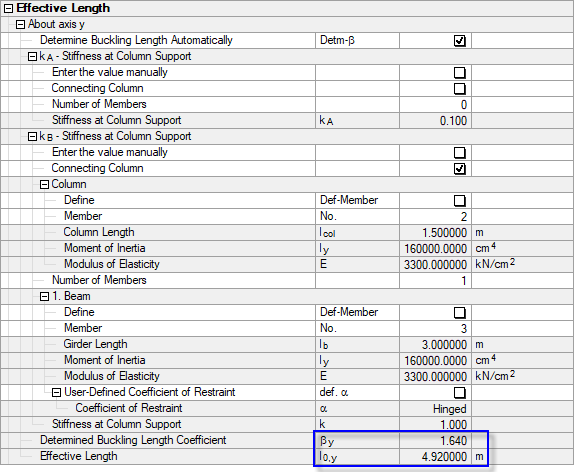
Figure 02 shows the structure to determine the effective length. The calculation is carried out in this example on member M1 for buckling around the y-axis.
Figure 03 shows the values determined with RF-/CONCRETE Columns.


.png?mw=600&hash=49b6a289915d28aa461360f7308b092631b1446e)


