Differential Equation of Bending Line for Applied Imperfections
Differential Equation of Bending Line for Applied Imperfections


Duration: 00:38:54 min
Duration: 00:00:19 min
Duration: 00:03:54 min
Duration: 00:00:48 min
Duration: 00:01:00 min

Duration: 01:06:55 min
Duration: 00:01:12 min
Duration: 00:00:22 min

Duration: 00:00:22 min


Prof._Dr.-Ing._G._Nonhoff__LI.jpg?mw=350&hash=3352d710a6bc7f4fed3f07a280a700972f70f6aa)


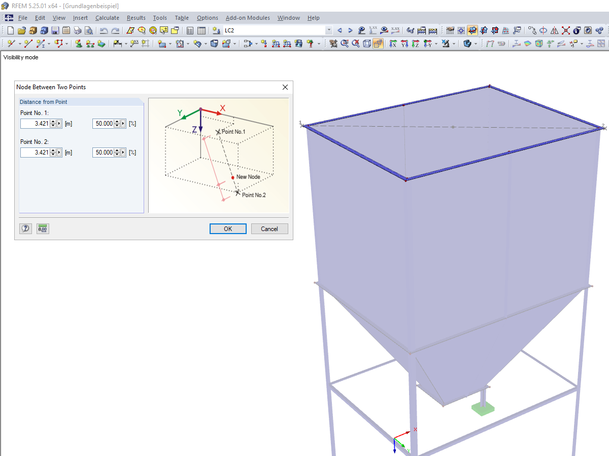
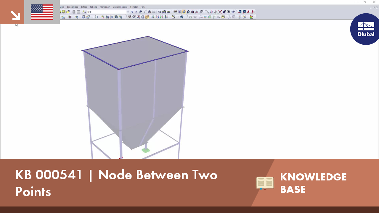
Until now, if you wanted to determine the centroid of a rectangle, it was necessary to define a line from one corner point to the diagonally opposite point. You obtained the centroid by dividing this line. In RFEM 5 and RSTAB 8, you now have the possibility to create a node between two points. Thus, it is sufficient to select the corner points; then you can determine the distance in absolute or relative values.
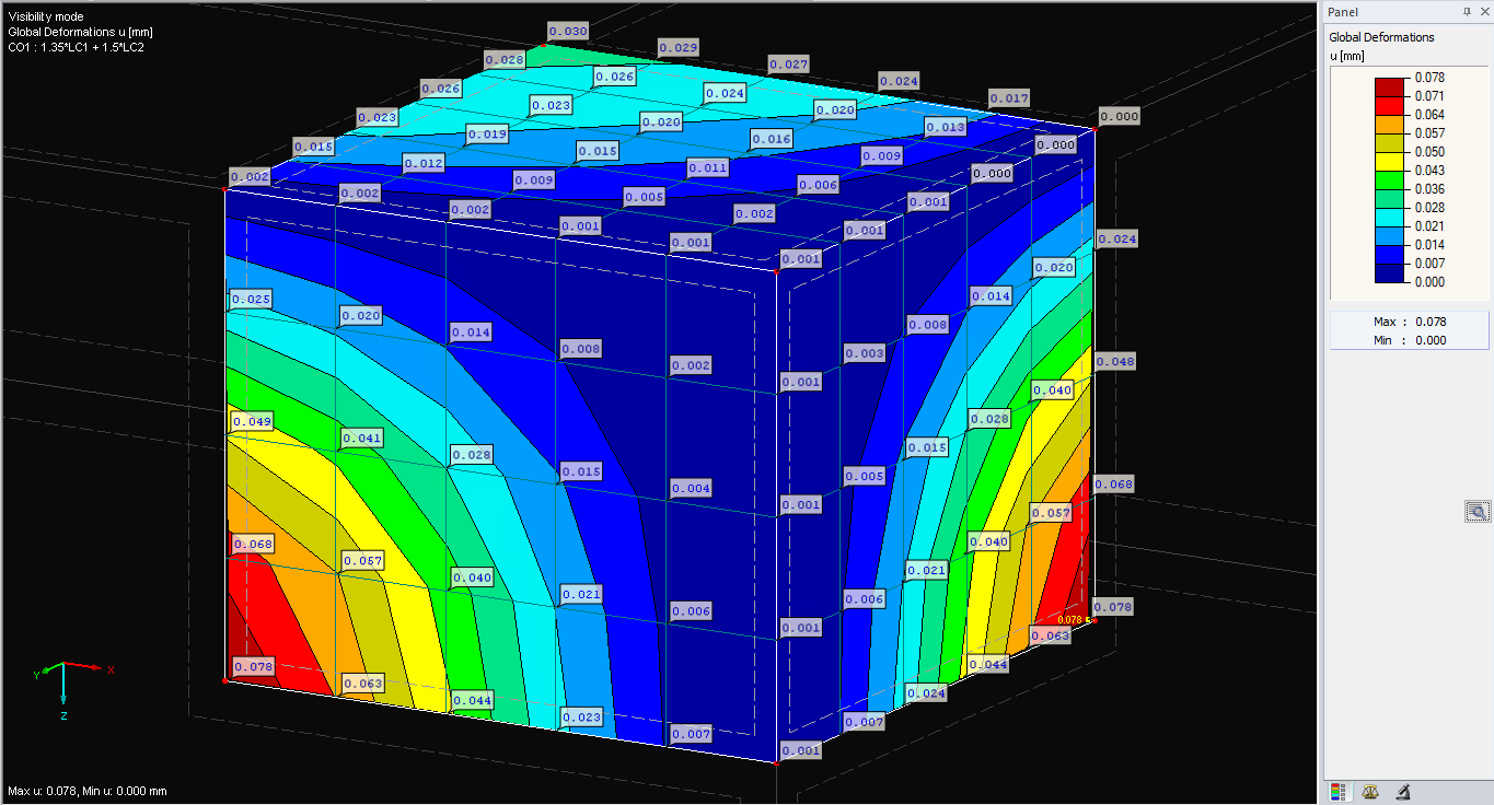
The deformations of the FE nodes are always the first result of an FE calculation. It is possible to calculate strains, internal forces, and stresses based on these deformations and the stiffness of the elements.

This article explores the importance of considering joint-structure interaction in modeling and design and how to do it in RFEM 6.
.png?mw=512&hash=4a84cbc5b1eacf1afb4217e8e43c5cb50ed8d827)
This article provides a comprehensive overview of essential seismic analysis methods, explaining their principles and applications, as well as the scenarios in which they are most effective


Want to automatically consider steel joint stiffness in your global RFEM model? Utilize the Steel Joints add-on!
Activate joint-structure interaction in the stiffness analysis of your steel joints. Hinges with springs are then automatically generated in the global model and included in subsequent calculations.

In the ultimate configuration of the steel joint design, you have the option to modify the limit plastic strain for welds.

The "Base Plate" component allows you to design base plate connections with cast-in anchors. In this case, plates, welds, anchorages, and steel-concrete interaction are analyzed.

In the "Edit Section" dialog box, you can display the buckling shapes of the Finite Strip Method (FSM) as a 3D graphic.
I want to create a mapped mesh for a circular hole plate. Is it possible to generate such a meshing in RFEM?
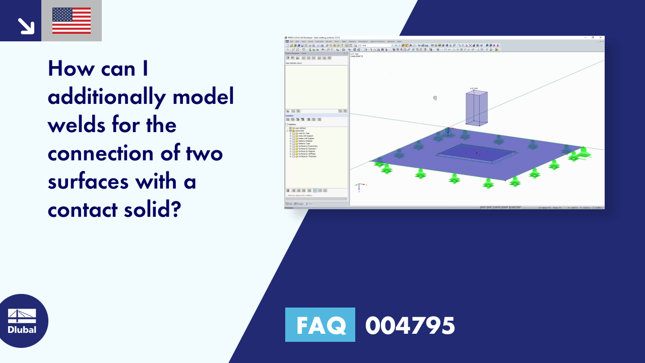
How can I additionally model welds for the connection of two surfaces with a contact solid?
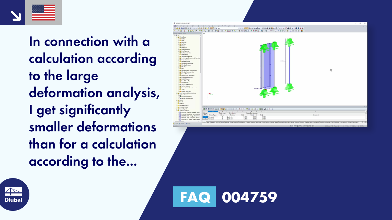
In connection with a calculation according to the large deformation analysis, I get significantly smaller deformations than for a calculation according to the linear static or second-order analysis. How can that be?
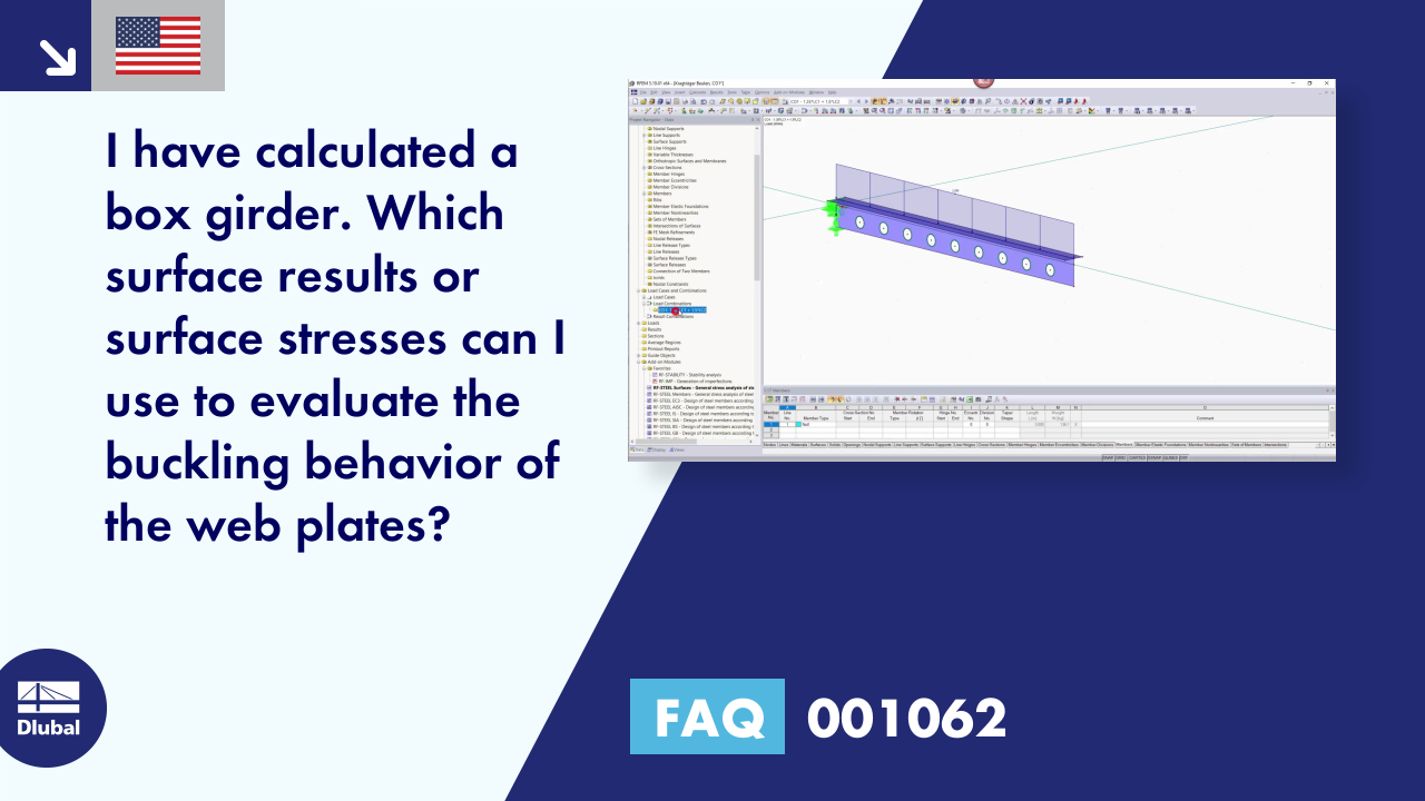
I have calculated a box girder. Which surface results or surface stresses can I use to evaluate the buckling behavior of the web plates?
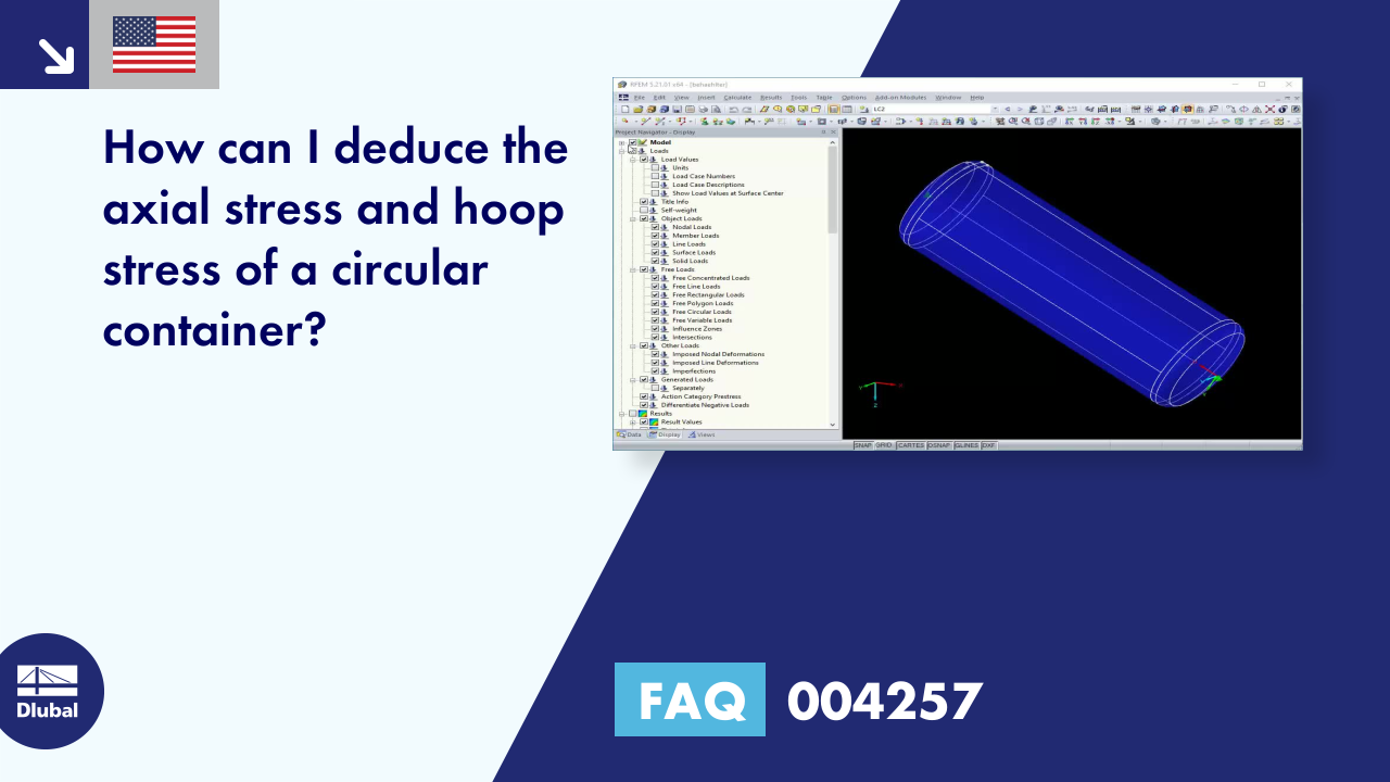
How can I deduce the axial stress and hoop stress of a circular container?
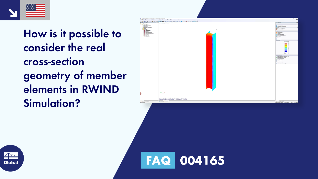
How is it possible to consider the real cross-section geometry of member elements in RWIND Simulation?


_1.jpg?mw=350&hash=ab2086621f4e50c8c8fb8f3c211a22bc246e0552)


