Question
It is not possible to create a rib on certain lines in my model. Several error messages appear.
Answer:
In most cases, there is a hinged connection between the ceilings or walls in order to prevent the moments from the ceiling slab from being transferred into the walls. If there are also a line hinge and a downstand beam (rib) on the same line, the surface to which the line hinge was assigned is highly important.Solution
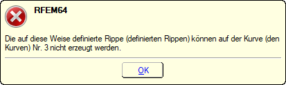
Since the rib is usually assigned to the ceiling slab, the line hinge should be assigned to the wall (see Image 01). If this is not the case, an error message appears (see Image 02), and the creation of the rib must be aborted.
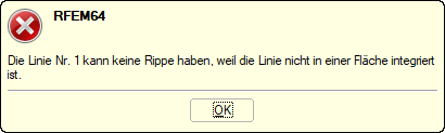
The same applies to the line hinges on free plate edges. If a line hinge has been created by mistake, an error message also appears when creating the rib (see Image 03 and Image 04).
Do you have any questions?
![Deformation Without Adjacent Settlement](/en/webimage/011759/2564745/01-de.png?mw=512&hash=9f2525444a7414dfb1c05a73e375e9c4fe4f47b1)
Settlement within a structural system can also affect the surrounding structures. The adjacent settlement of separated slabs can be considered with RF-SOILIN using a small trick.
![Floor Slab with Racking Loads](/en/webimage/011117/2470737/01-en.png?mw=512&hash=65e98cfe859ce35a3e3e9da47a0ef9335401520e)
Describing the procedure for the serviceability limit state design of a floor slab made of steel fiber reinforced concrete. This article shows how to perform the corresponding design for the SLS by means of the iteratively determined FEA results.
![Base Plate with FE Mesh Refinements and Shelf Support Loads](/en/webimage/008690/2217100/01-_en.png?mw=512&hash=54c6d3ca8325d85ed7a00ec6f5095c0a2863158d)
Steel-fiber-reinforced concrete is mainly used nowadays for industrial floors or hall floors, foundation plates with low loads, basement walls, and basement floors. Since the publication in 2010 of the first guideline about steel-fiber-reinforced concrete by the German Committee for Reinforced Concrete (DAfStb), a structural engineer can use standards for the design of the steel fiber-reinforced concrete composite material, which makes the use of fiber-reinforced concrete increasingly popular in construction. This article describes the nonlinear calculation of a foundation plate made of steel fiber-reinforced concrete in the ultimate limit state with the FEA software RFEM.
![Design Spectrum](/en/webimage/008895/600979/KB_1578_01_EN.png?mw=512&hash=b3d405a4bf6254358f6c2194c96b38a692c0d571)
DIN EN 1998-1 with the National Annex DIN EN 1998-1/NA specifies how to determine seismic loads. The standard applies to structural engineering in seismic areas.
![Feature 002828 | Fire Design of Slabs and Walls According to Simplified Table Method](/en/webimage/050837/3925042/50837.png?mw=512&hash=b06639a36ab8b62ab6d08e08552a5ec274469a37)
In the Concrete Design add-on for RFEM 6, you can perform the fire design of reinforced concrete slabs and walls according to the simplified table method (EN 1992‑1‑2, Section 5.4.2 and Tables 5.8 and 5.9).
![Feature 002825 | Shear Walls and Deep Beams Consisting of Members](/en/webimage/050709/3925056/50709.png?mw=512&hash=8e57b70946dcc367584aee1ee2d82b3efafa652f)
When generating shear walls and deep beams, you can assign not only surfaces and cells, but also members.
![Feature 002826 | Punching Shear Reinforcement](/en/webimage/050658/3936123/50658.png?mw=512&hash=ae20d4ca78cdf203a2c2d3ccbb7daa0f324da77a)
In the Concrete Design add-on, you have the option to define an existing vertically oriented punching shear reinforcement. This is then taken into account in the punching shear design.
![Feature 002801 | Punching Shear Design for All Section Shapes](/en/webimage/048276/3861250/2024-05-01_15-05-25.png?mw=512&hash=7732dd7fd2a19d53a9f6f77a35896a7c3676cff2)
Do you have individual column sections and angled wall geometries, and need punching shear design for them?
No problem. In RFEM 6, you can perform punching shear design not only for rectangular and circular sections, but for any cross-section shape.
I just have to calculate an open hall with low roof loads and, compared to them, relatively high wind loads. In theory, it is necessary to perform the lateral-torsional buckling design of the bottom flange. Unfortunately, the combination 1.0*G + 1.5*W is missing.
Recommended Products for You