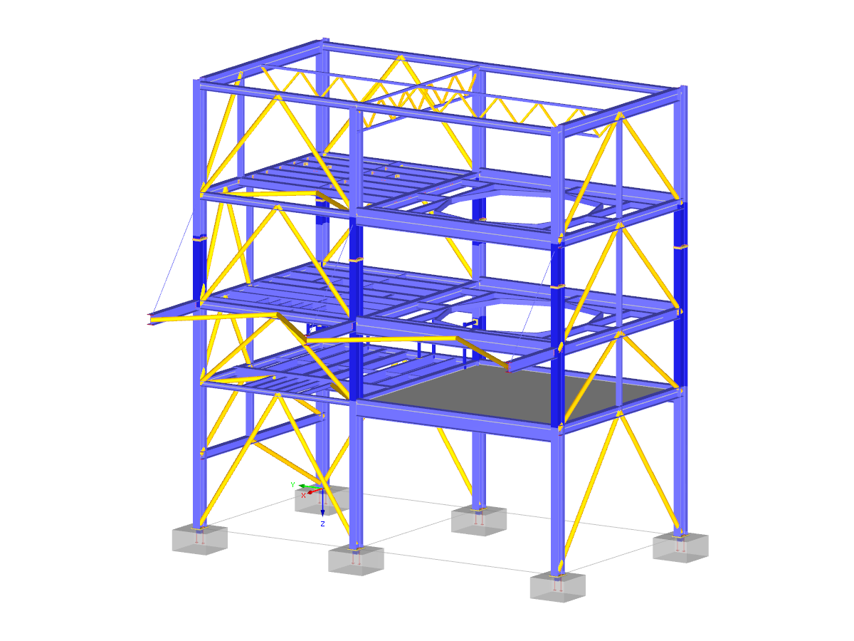
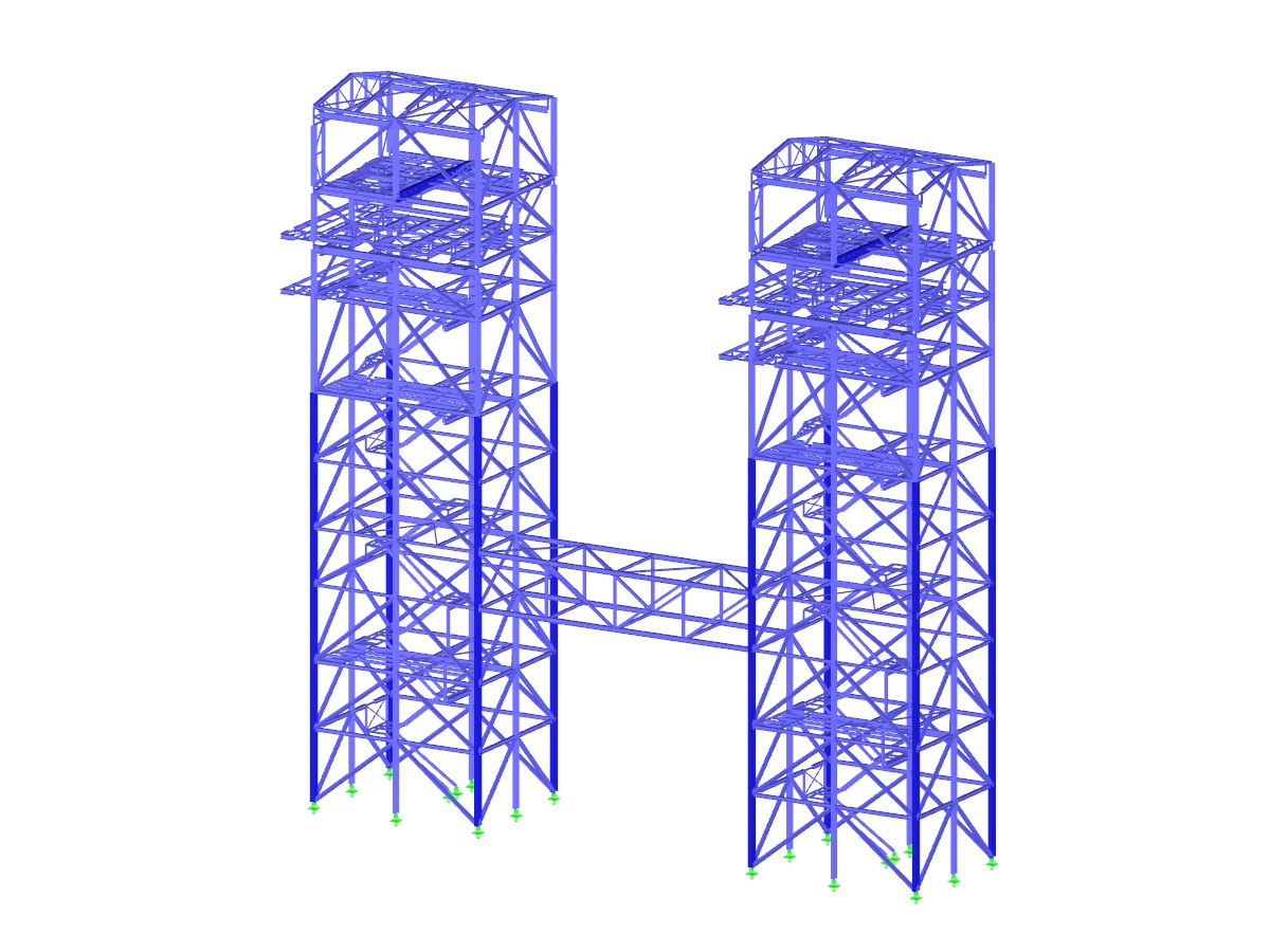
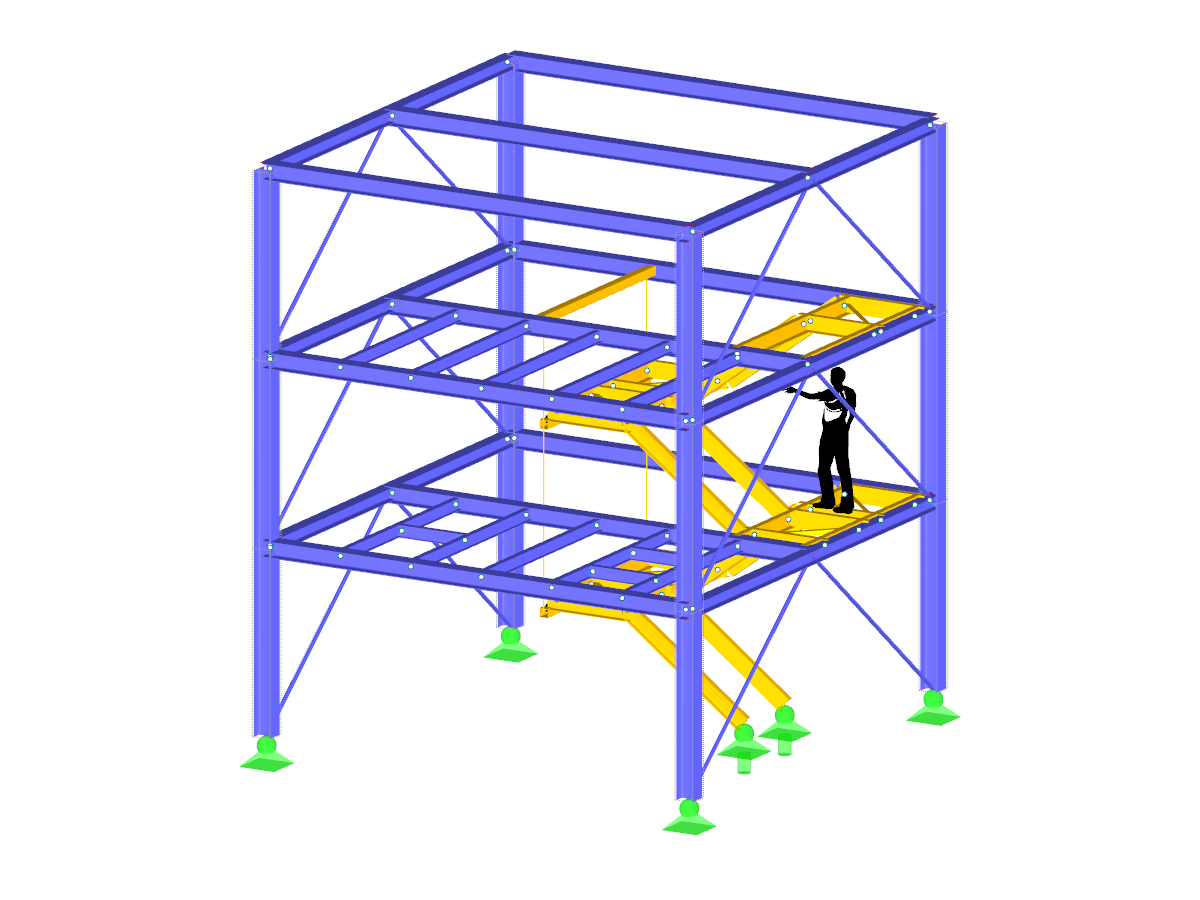
Model of a conveyor bridge for wind simulation on belt conveyors.
Model Used in
Belt Conveyor
Number of Nodes | 867 |
Number of Lines | 1235 |
Number of Members | 64 |
Number of Surfaces | 448 |
Number of Load Cases | 9 |
Total Weight | 6.518 tons |
Dimensions (Metric) | 12.284 x 2.941 x 2.900 m |
Dimensions (Imperial) | 40.3 x 9.65 x 9.51 feet |
Program Version | 5.23.00 |
You can download this structural model to use it for training purposes or for your projects. However, we do not assume any guarantee or liability for the accuracy or completeness of the model.
Related Models
3250x
167x
![Load Case 1](/en/webimage/009079/499648/01-de.png?mw=512&hash=9f2525444a7414dfb1c05a73e375e9c4fe4f47b1)
The design of a torsional loaded beam according to AISC Design Guide 9 will be shown, based on a verification example. The design will be performed with the RF‑STEEL AISC add-on module and the RF‑STEEL Warping Torsion module extension with 7 degrees of freedom.
![Bending Moment Distribution on Entire System and Separated Structure](/en/webimage/009670/2419890/01-en-png-png.png?mw=512&hash=6ca63b32e8ca5da057de21c4f204d41103e6fe20)
This article explains how to determine loads on the basis of the internal force situations defined in the RF‑/STEEL Warping Torsion extension of the RF‑/STEEL EC3 add-on module. Since this new program also allows you to analyze extracted chain-like beam structures in addition to entire chain-like beam structures, it is necessary to determine the loads of the partial structure separately. To do this, a special transformation function has been developed that determines new loads of all partial structures (depending on the internal forces calculated in RFEM/RSTAB) according to each load situation for geometrically nonlinear warping torsion analysis with seven degrees of freedom.
![System and Loading](/en/webimage/008936/577926/01-en.png?mw=512&hash=65e98cfe859ce35a3e3e9da47a0ef9335401520e)
The critical factor for lateral-torsional buckling or the critical buckling moment of a single-span beam will be compared according to different stability analysis methods.
![KB 001883 | Plate Girder Design According to AISC 360-22 in RFEM 6](/en/webimage/051561/3980997/im1.png?mw=512&hash=b8237709c4f30213fac51d86d32a42bddde72f03)
Plate girder is an economical choice for long spans construction. I-section steel plate girder typically has a deep web to maximize its shear capacity and flange separation, yet thin web to minimize the self-weight. Due to its large height-to-thickness (h/tw) ratio, transverse stiffeners may be required to stiffen the slender web.
![RF-/STEEL Fatigue Members Add-on Module for RFEM/RSTAB | Fatigue Design of Members According to EN 1993-1-9](/en/webimage/002826/2983174/Kranbahn_Ermüdung_fertig_(4).png?mw=512&hash=db4e9566a195dfbcd88691b0322a93a7e4b79a9d)
- Full integration in RFEM/RSTAB including import of all relevant information and internal forces
- Determination of stress ranges for the available load cases and load or result combinations
- Free assignment of detail categories on the available stress points of the cross-section
- User-defined specification of damage equivalent factors
- Design of members and sets of members according to EN 1993-1-9
- Optimization of cross-sections with the option to transfer the data to RFEM/RSTAB
- Detailed result documentation with references to design equations used
- Various filter and sorting options of results, including result lists by member, cross-sections, x-location, or by load case, load and result combination
- Visualization of the design criterion on RFEM/RSTAB model
- Data export to MS Excel
![RF-/STEEL Plasticity Add-on Module for RFEM/RSTAB | Plastic Design of Cross-Sections](/en/webimage/002822/3468568/torsional_buckling.png?mw=512&hash=d16e025385b7e1da0e5d703f4cdda891f3986fe8)
- Applicable for members defined as sets of members
- Separate solver that considers 7 deformation directions (ux, uy, uz, φx, φy, φz, ω) or 8 internal forces (N, Vu, Vv, Mt,pri, Mt,sec, Mu, Mv, Mω)
- Nonlinear design according to second-order analysis
- Input of imperfections
- Calculation of critical load factors and buckling mode shapes as well as the visualization of them (incl. warping)
- Integration into member design in the RF-/STEEL AISC and RF‑/STEEL EC3 add‑on modules
- Available for all thin‑walled steel cross‑sections
![Add-on "Steel Joints for RFEM 6" | Component Library](/en/webimage/043097/3898884/steel_joints_components.png?mw=512&hash=e4f835906155863fc7019d5043b22e553dc766f9)
- Numerous component types, such as base and end plates, web angles, fin plates, gusset plates, stiffeners, tapers, or ribs for easy input of typical connection situations
- Universally applicable basic components (such as plates, welds, bolts, auxiliary planes) for modeling complex connection situations
- Graphical display of the connection geometry with dynamic updating during the input
- Wide range of cross-section shapes: I-sections, U-sections, angles, T-sections, hollow sections, built-up cross-sections and thin-walled sections
- Library in the Dlubal Center with a large number of program-side template connections, including user-defined templates
- Automatic adaptation of the connection geometry based on the relative arrangement of the components to each other – even in case of subsequent editing of the structural components
![Feature 002820 | Limit Plastic Strain for Welds](/en/webimage/050344/3881226/1.png?mw=512&hash=9d7f6c198b6d4ae6ee8f2fa8bca75f85579e14c9)
In the ultimate configuration of the steel joint design, you have the option to modify the limit plastic strain for welds.
Recommended Products for You