How may I help you?
Do you have any questions about Dlubal products or need assistance in selecting the right one for your project?
I'm here to help. You can easily reach me through the contact options provided below.
Looking forward to hearing from you!
Amy Heilig, PE
CEO – USA Office | Sales & Technical Support Engineer


Intuitive User Interface with Individual Customization Options
Total items: 6

Intuitive User Interface
A great strength of the Dlubal programs is their intuitive, easy-to-learn operation. RFEM 6 is no exception. Create your structure in a user interface usual for CAD or via tables. By right-clicking the graphical or navigator objects, a shortcut menu appears, which facilitates you creating or editing the objects. Due to the intuitive user interface, you can create structural and loading objects in a very short time.
Go to Explanatory Video
Multilingual Program Operation
The Dlubal programs reach customers from all over the world. Therefore, the program can be operated in the following languages: English, German, French, Spanish, Portuguese, Italian, Czech, Polish, Russian, Chinese, and Dutch.
Go to Explanatory Video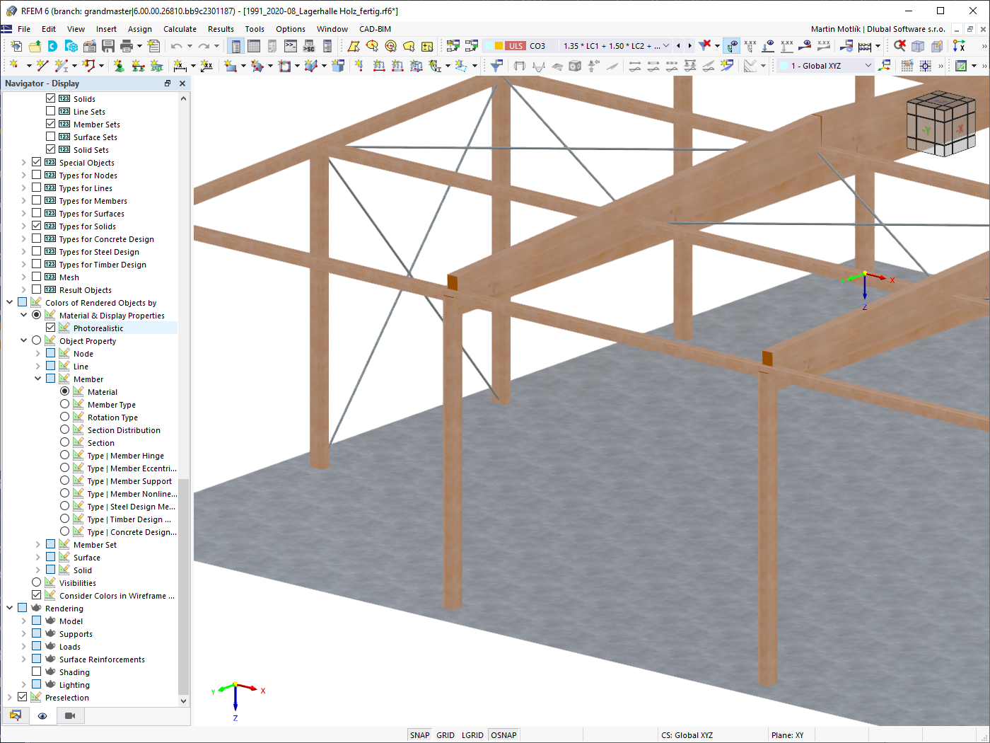
Photorealistic Rendering
Always keep an eye on your model. Due to the photorealistic rendering (optionally with textures), you always have immediate control of your input. You can freely adjust the display colors and save them separately for screen and printout.
Go to Explanatory Video
RFEM 6 | Display properties
It is possible to assign different colors to various objects of a structure in order to make the rendering display of the structure more clearly arranged.
A distinction is made between the various object properties of nodes, lines, members, member sets, surfaces, and solids. Moreover, the model can be displayed in photorealistic rendering.
Go to Explanatory Video

Displaying and Hiding Objects
Work more efficiently by freely adjusting the display of your model. You can selectively display or hide various objects, such as nodes, members, supports, and others. Dimension your model by using lines, arcs, inclinations, or height elevations. Freely created guidelines, sections, and comments facilitate you the input and evaluation. You can also display or hide the guide objects individually.
Go to Explanatory Video
Global Unit Settings
You can keep track of things with just a few clicks. A global dialog box manages the units for input data, loads, and results in RFEM or RSTAB, as well as in all add-ons.
You can save the settings and import them again later. In this way, it is possible for you to use different sections in steel and reinforced concrete structures, for example.
Go to Explanatory VideoCalculate Your Price
Total Amount 4,170.00 USD
The price is valid for United States.


Length: 01:06:40 min

Length: 00:01:58 min

Length: 01:08:53 min

Length: 00:01:18 min

Length: 01:00:08 min

Length: 00:00:34 min

Length: 00:00:42 min

Length: 00:00:42 min

Length: 00:52:56 min


Plate girder is an economical choice for long spans construction. I-section steel plate girder typically has a deep web to maximize its shear capacity and flange separation, yet thin web to minimize the self-weight. Due to its large height-to-thickness (h/tw) ratio, transverse stiffeners may be required to stiffen the slender web.

Understanding steel connection rigidity is crucial in structural design. Often, connections are treated as strictly pinned or rigid, but this can lead to uneconomical or even dangerous designs. Explore how Dlubal Software's RFEM and Steel Joints add-on help verify connection stiffness and moment resistance, ensuring safer and more economical designs.
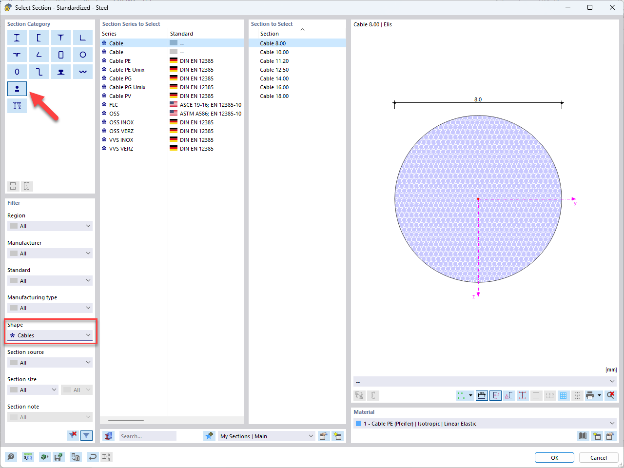
In this article, you will learn how to model and design cable structures in RFEM 6 or RSTAB 9.

This article describes and explains the influence of bending stiffness of cables on their internal forces. Furthermore, the text provides information on how this influence can be reduced.


- Numerous component types, such as base and end plates, web angles, fin plates, gusset plates, stiffeners, tapers, or ribs for easy input of typical connection situations
- Universally applicable basic components (such as plates, welds, bolts, auxiliary planes) for modeling complex connection situations
- Graphical display of the connection geometry with dynamic updating during the input
- Wide range of cross-section shapes: I-sections, U-sections, angles, T-sections, hollow sections, built-up cross-sections and thin-walled sections
- Library in the Dlubal Center with a large number of program-side template connections, including user-defined templates
- Automatic adaptation of the connection geometry based on the relative arrangement of the components to each other – even in case of subsequent editing of the structural components

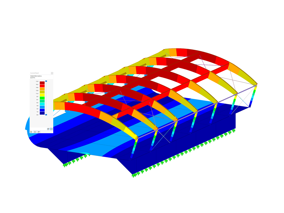
In the Navigator – Results, you can select the design situations for which you want to display the add-on results graphically.

For design objects, you can optionally display sags or extreme results.

You can add dynamic shadows in the rendering mode. In the shortcut menu, you can use sliders to change the main light position.
How can I automatically unify two points that are close to each other?
What is the component-based finite element method (CBFEM)?
Is it possible to define one or more nodes on one or more members automatically?
I would like to use my account for RFEM 6 / RSTAB 9, but apparently I'm not authorized to do so. Is there any way to allow this?
How can I export the deformed geometry of an RFEM 6 model?
Can I calculate a composite beam with RFEM 6?


