Do you have any questions about Dlubal products or need assistance in selecting the right one for your project?
I'm here to help. You can easily reach me through the contact options provided below.
Looking forward to hearing from you!
Amy Heilig, PE
CEO – USA Subsidiary | Sales Engineer

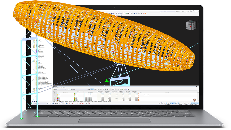
Software for Timber and Wood Structures
Questions about timber structures? Mia answers immediately!


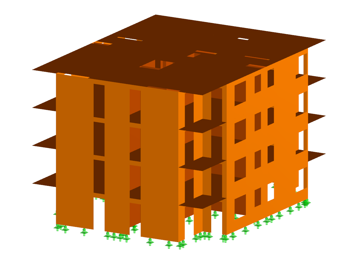
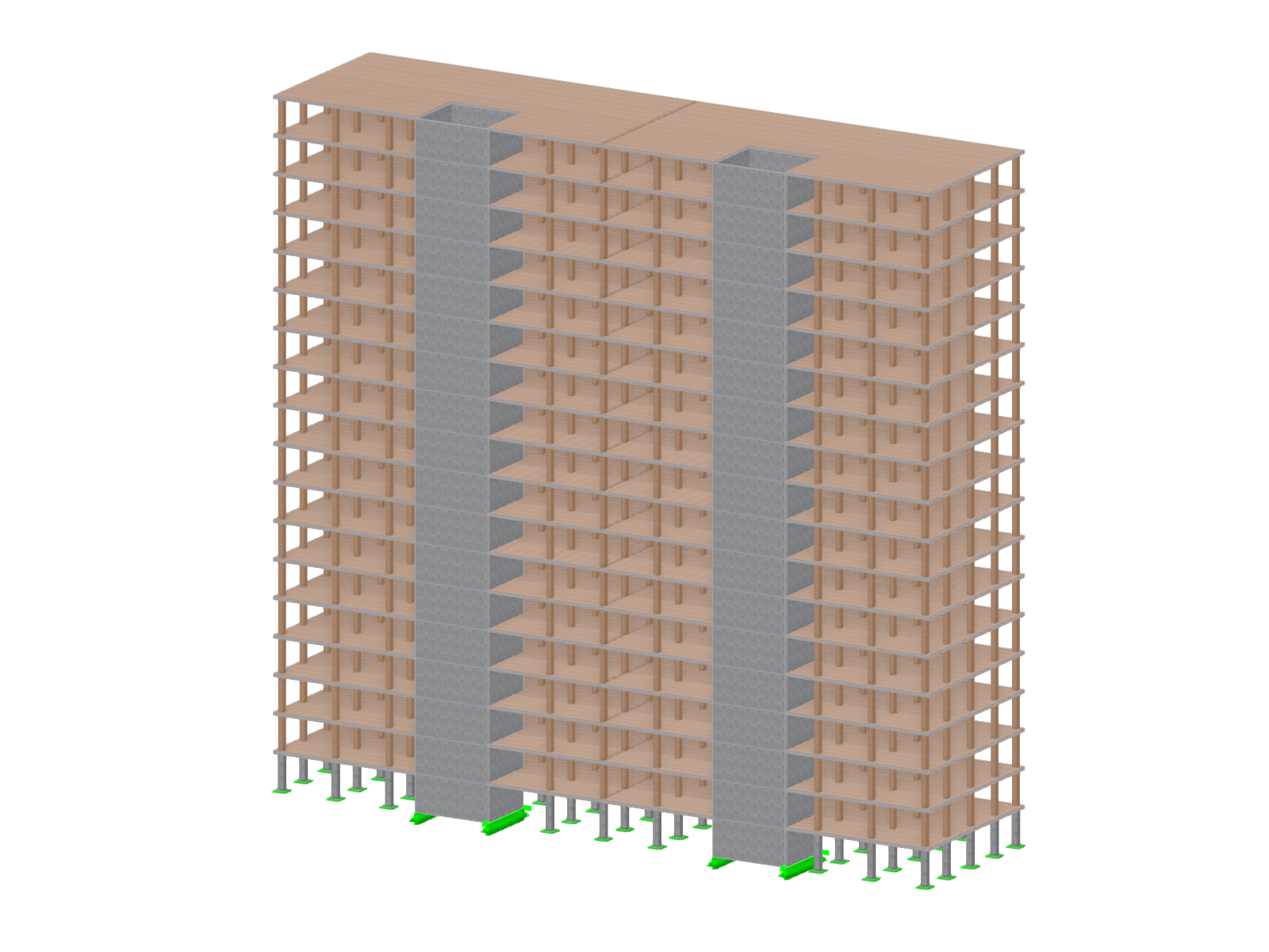
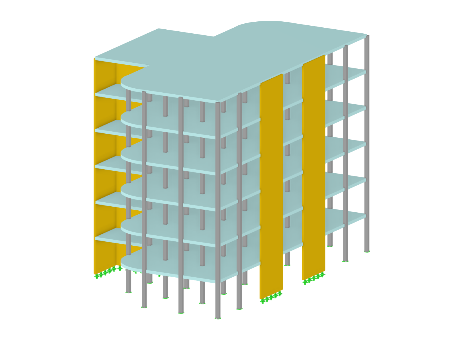
Structural Models | Timber Structures

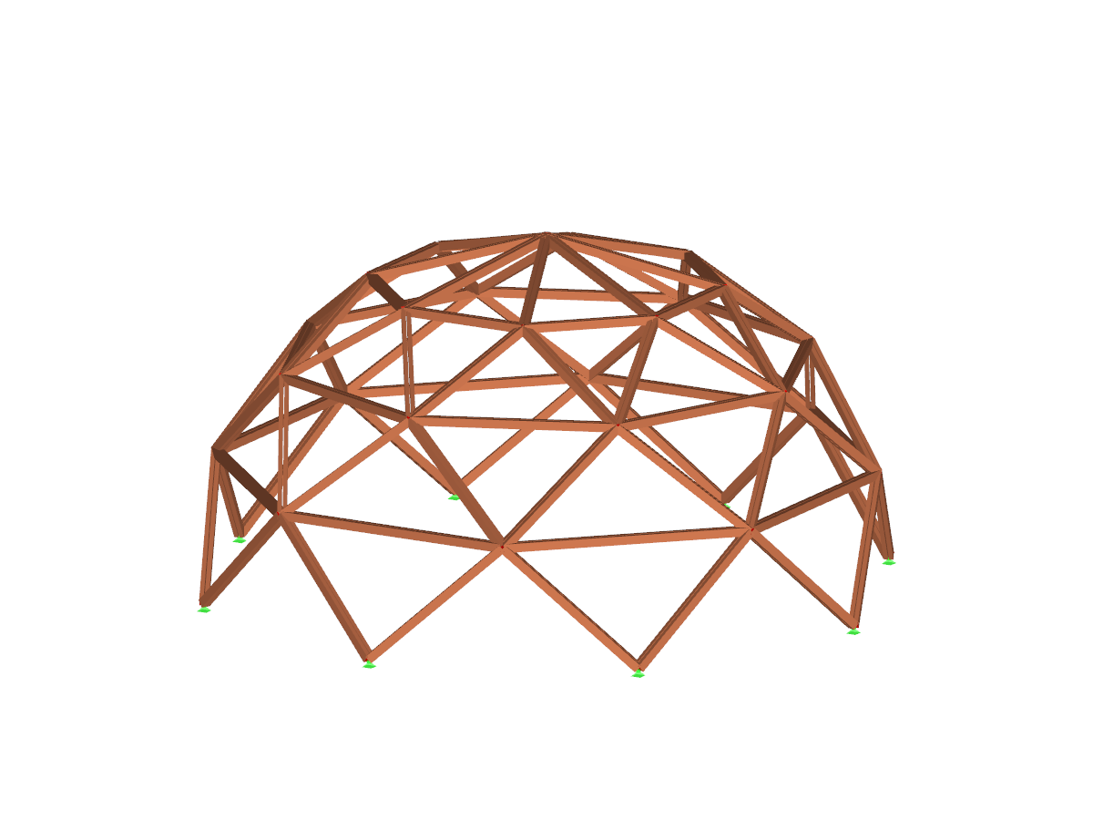
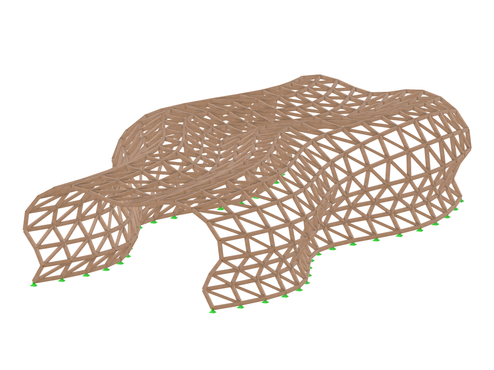

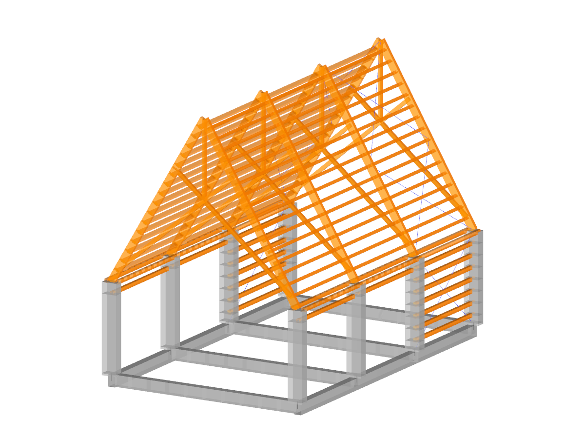
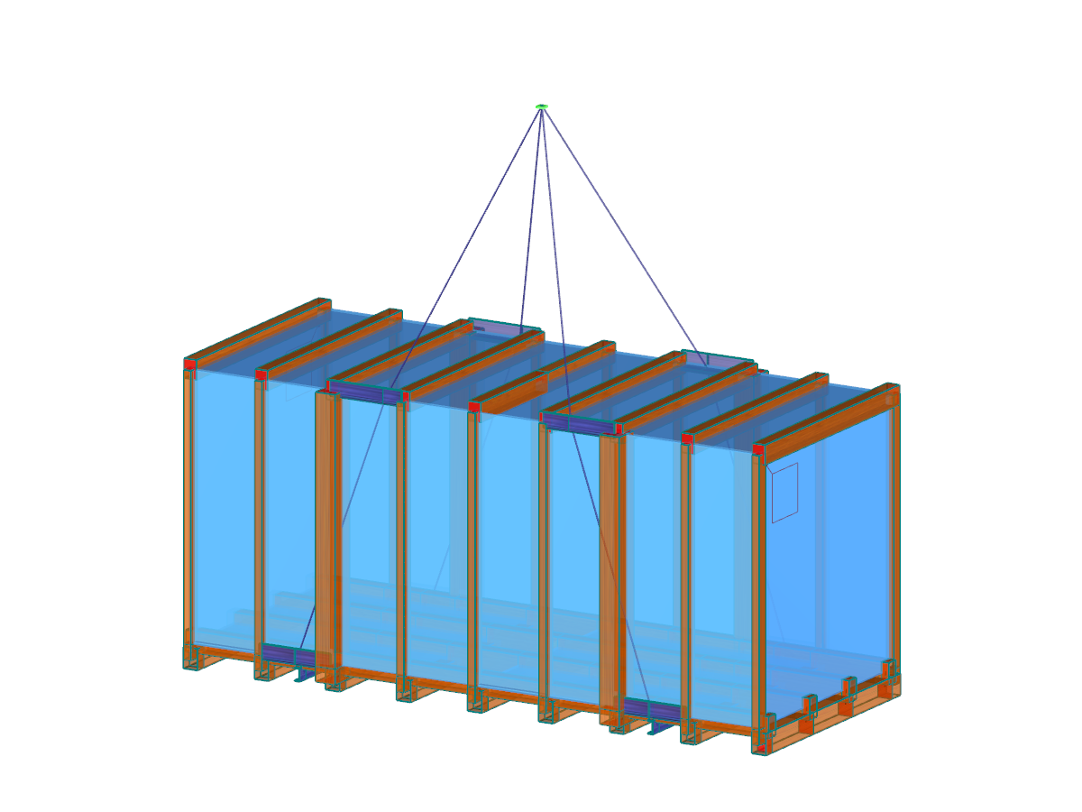
Main Program RFEM or RSTAB

Recommended Add-on Products for Timber Structures

Multilayer Surfaces such as CLT and Timber Frame Walls
Multilayer Surfaces (e.g. Laminate, CLT) for RFEM 6
Add-On
The "Multilayer Surfaces" add-on for RFEM 6 optimizes the modeling and analysis of multilayer timber structures, ideal for cross-laminated timber and timber stud walls. It effectively supports the structural analysis of prefabricated timber panels.
Hybrid Timber Construction with Complementary Materials
Building Model for RFEM 6
Add-On
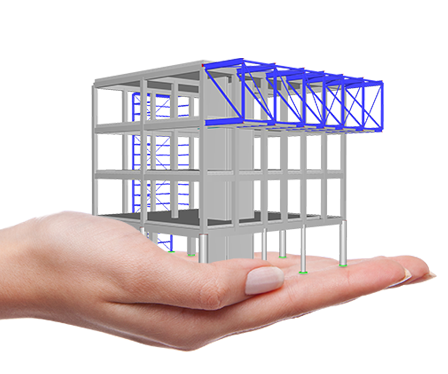
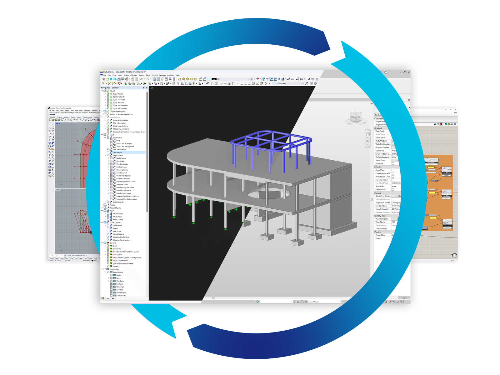
The "Building Model" add-on simplifies the modeling and analysis of timber buildings. It speeds up the creation of building models and automatizes the load generation, ideal for demanding structural timber projects.
Construction Stages
Construction Stages Analysis (CSA) for RFEM 6
Add-On
The Construction Stages Analysis (CSA) add-on allows for considering the construction process of structures (member, surface, and solid structures) in RFEM.
Optimization of Model Parameters
Optimization & Cost / CO2 Emission Estimation for RFEM 6
Add-On
The add-on uses particle swarm optimization (PSO) to determine optimal parameters for parameterized models based on weight, cost, or CO2 emissions.
Response Spectrum Analysis
Response Spectrum Analysis for RFEM 6
Add-On
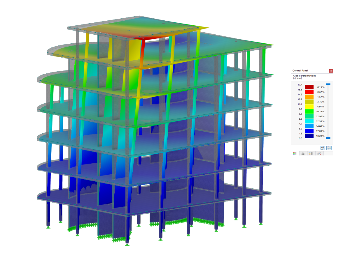
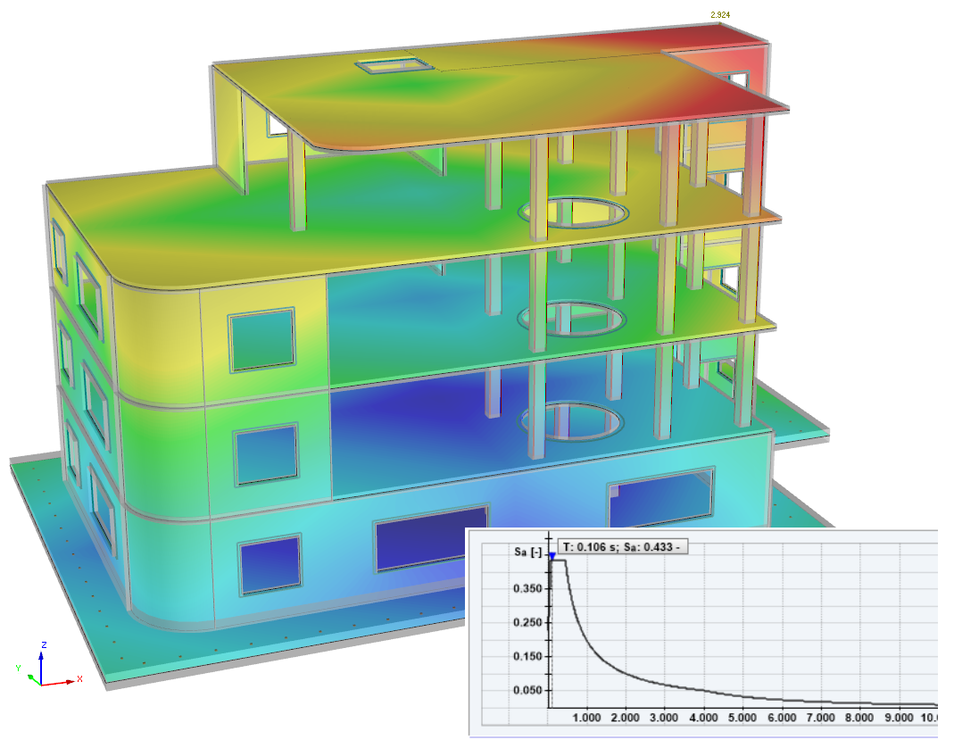
The Response Spectrum Analysis add-on performs seismic analysis using multi-modal response spectrum analysis. The spectra required for this can be created in compliance with the standards or can be user-defined. The equivalent static forces are generated from them. The add-on includes an extensive library of accelerograms from seismic zones that can be used to generate the response spectra.
Support and Learning
We provide professional support and many services in order to help you with finding a quick and efficient solution for your projects.
Optimizing Projects with RFEM 6 by Dlubal Software: Investment Without Hesitation
After researching the with structural analysis software market, I finally decided to choose RFEM by Dlubal for the design of all types of timber structures (traditional framework, glued-laminated timber, timber-framed walls, mechanically welded fittings, and so on). The software is quite easy to learn and relatively intuitive; I don't need any training.
If you get stuck on a topic, you can rely on fast and efficient support. Moreover, there is multi-material software that can solve all the issues you encounter.
In other words, go ahead and invest!
Thibaut DUSSART
Girard Ouvrages Bois
1 Avenue du General Patton, 45330, Malesherbes
France
RFEM 6 by Dlubal: Best Choice for 3D Timber Design According to Swiss SIA Standards
After analyzing the other structural analysis software offers on the market, we chose Dlubal's RFEM to calculate our three-dimensional timber structures.
This is the software that we believe is best suited for structural analysis and design according to the Swiss SIA standards.
The user interface is clear and intuitive, the results are displayed in detail, they can be edited and checked manually, which minimizes the effect of a "black box" and supports engineers in their decision-making.
The technical support team is attentive to our needs, reacting quickly and competently, responsive and competent, which confirms our choice.
Alexandre Angéloz
MP Ingenieurs Conseils SA
Rue du Centre 16, 1023, Crissier
Switzerland
.png?mw=192&hash=f63e4a3f1836233005de32f60201d5392e507cf1)

John W. Olver Design Building, University of Massachusetts, USA
The building is largely exposed and consists of 5-ply CLT concrete composite floor panels supported by a glulam post and beam structure.
-
Project Location
Amherst, MA, USA
-
Software
RFEM 5
More About Customer Project
© Alex Schreyer / UMass


Integrated Standards for Timber Design
Standards for Timber Design
Annexes for EN 1995-1-1
My name is Mia: Your 24/7 AI Assistant
Do you have any questions about timber structures?
.png?mw=80&hash=24e105a767cf2e175614b729c2d2fa1673e4e81b)
Didn't receive assistance from Mia? Please reach out to our support teams:
Technical Support | Sales Team
Technical Support | Sales Team

Duration: 01:10:42 min
Duration: 00:01:22 min

Duration: 01:07:03 min

Duration: 00:01:33 min


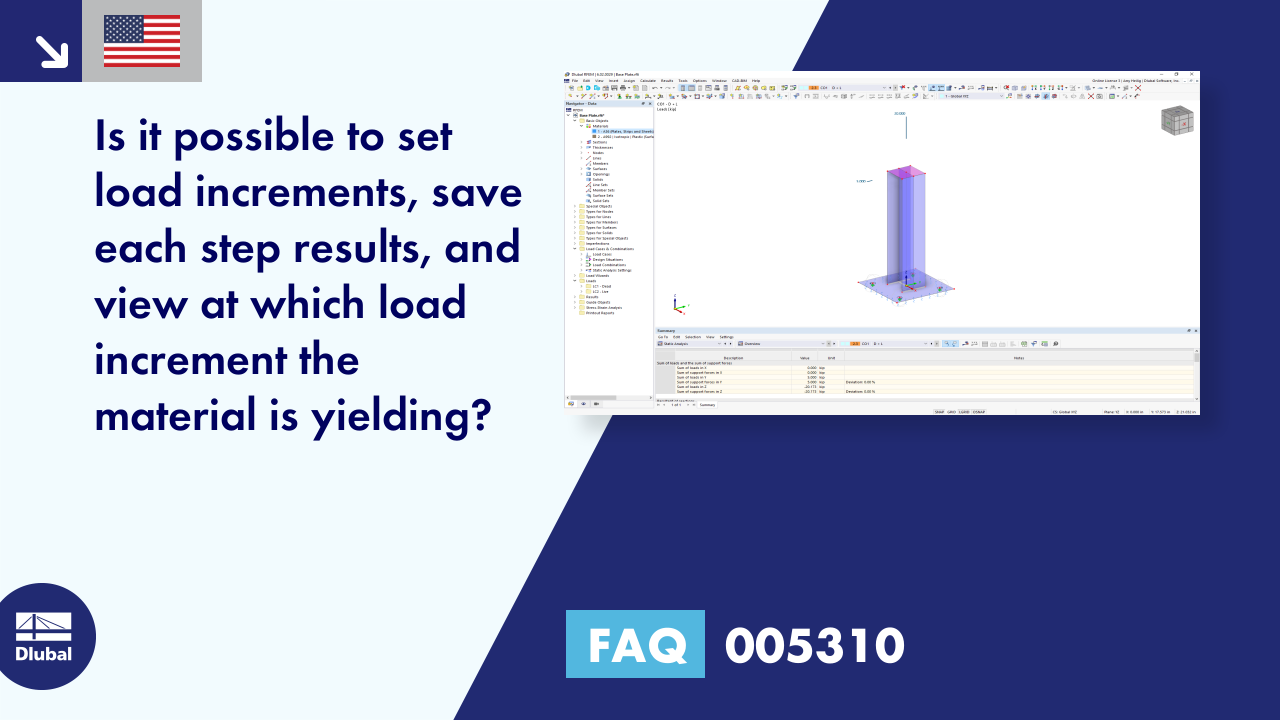
For reinforced concrete components and structures whose structural behavior is significantly influenced by the second-order effects, Eurocode 2 provides the general method based on a nonlinear determination of internal forces according to the second-order analysis (5.8.6), as well as an approximation method based on the nominal curvature (5.8.8).
The aim of this technical article is to perform a design according to the general design method of Eurocode 2, using the example of a slender reinforced concrete column.
The aim of this technical article is to perform a design according to the general design method of Eurocode 2, using the example of a slender reinforced concrete column.
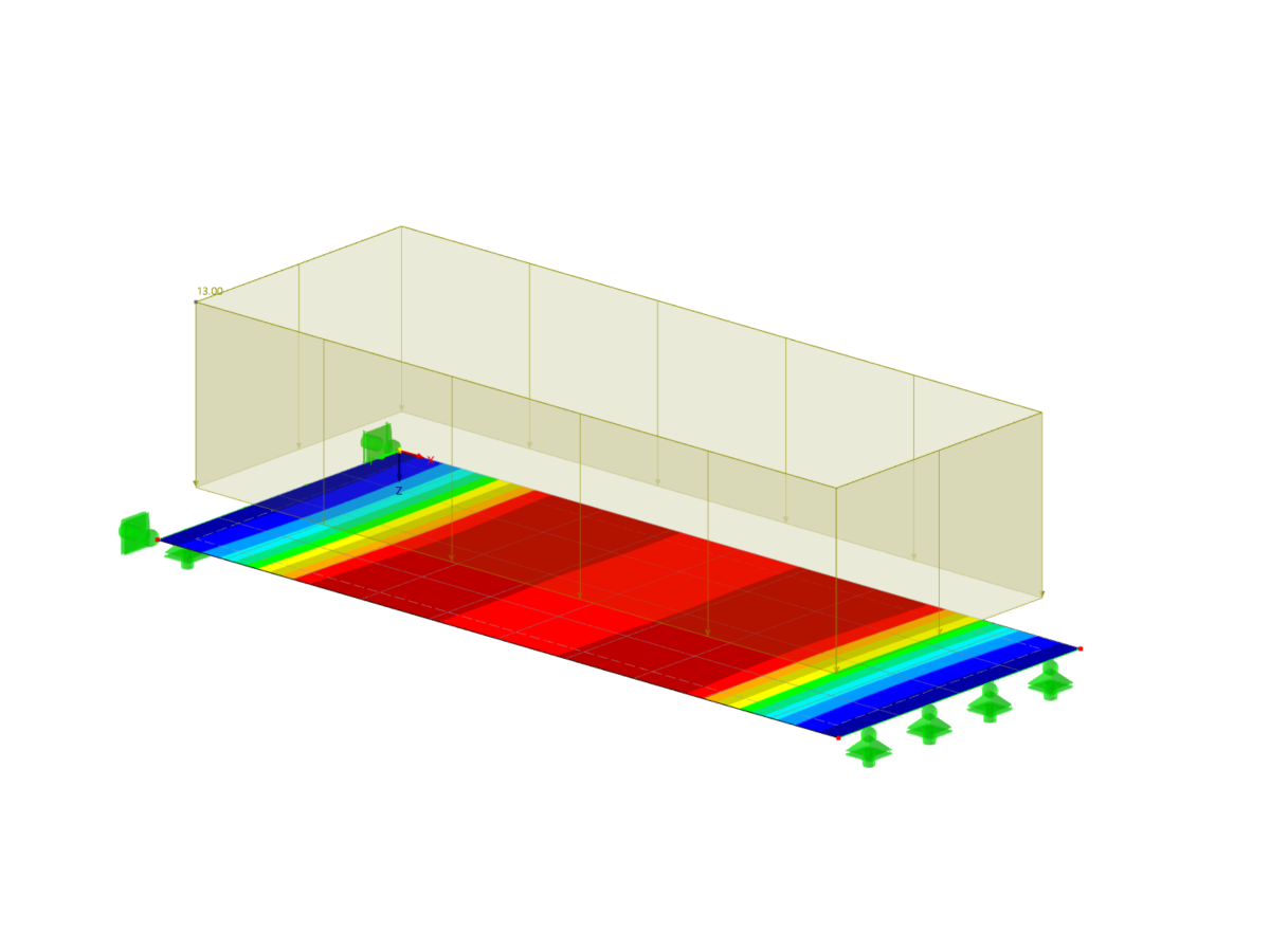
Using an example of a steel fiber-reinforced concrete slab, this article describes how the use of different integration methods and of a different number of integration points affects the calculation result.


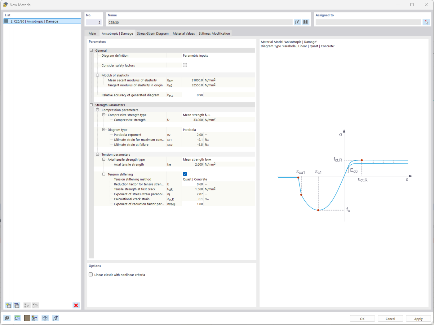
The "Nonlinear Material Behavior" add-on includes the Anistropic | Damage material model for concrete structural components. This material model allows you to consider concrete damage for members, surfaces, and solids.
You can define an individual stress-strain diagram via a table, use the parametric input to generate the stress-strain diagram, or use the predefined parameters from the standards. Furthermore, it is possible to consider the tension stiffening effect.
For the reinforcement, both nonlinear material models "Isotropic | Plastic (Members)" and "Isotropic | Nonlinear Elastic (Members)" are available.
It is possible to consider the long-term effects due to creep and shrinkage using the "Static Analysis | Creep & Shrinkage (Linear)" analysis type that has been recently released. Creep is taken into account by stretching the stress-strain diagram of the concrete using the factor (1+phi), and shrinkage is taken into account as the pre-strain of the concrete. More detailed time step analyses are possible using the "Time-Dependent Analysis (TDA)" add-on.
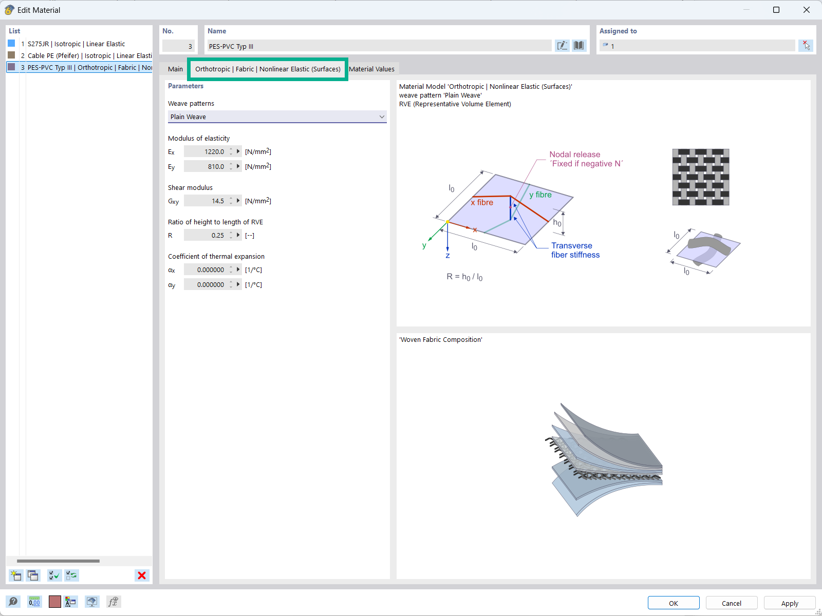
The "Orthotropic | Fabric | Nonlinear Elastic (Surfaces)" material model allows you to define prestressed fabric membranes using the representative microstructure-solid element model – RVE.
By considering the fabric geometry in the microstructure model, the corresponding transversal strain effect can now be considered for all force conditions in the membrane.
.png?mw=512&hash=57a05dc9f33b1949836c96669cadcdc6332b64e5)
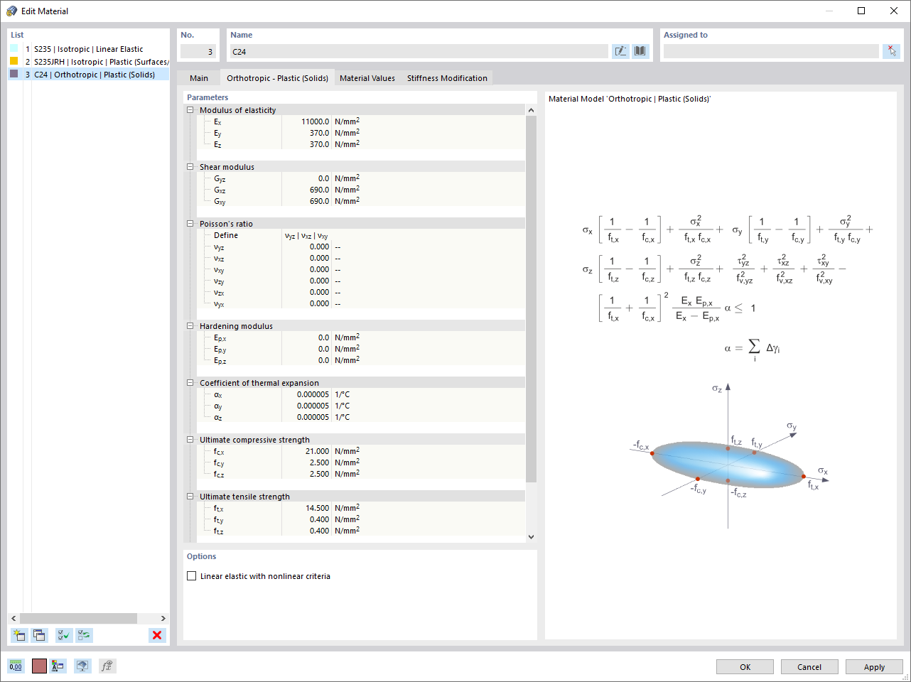
Are you familiar with the Tsai-Wu material model? It combines plastic and orthotropic properties, which allows for special modeling of materials with anisotropic characteristics, such as fiber-reinforced plastics or timber.
If the material is plastified, the stresses remain constant. The redistribution is carried out according to the stiffnesses available in the individual directions. The elastic area corresponds to the Orthotropic | Linear Elastic (Solids) material model. For the plastic area, the yielding according to Tsai-Wu applies:
All strengths are defined positively. You can imagine the stress criterion as an elliptical surface within a six-dimensional space of stresses. If one of the three stress components is applied as a constant value, the surface can be projected onto a three-dimensional stress space.
If the value for fy(σ), according to the Tsai-Wu equation, plane stress condition, is smaller than 1, the stresses are in the elastic zone. The plastic area is reached as soon as fy (σ) = 1; values greater than 1 are not allowed. The model behavior is ideal-plastic, which means there is no stiffening.

Did you know? In contrast to other material models, the stress-strain diagram for this material model is not antimetric to the origin. You can use this material model to simulate the behavior of steel fiber-reinforced concrete, for example. Further information about modeling steel fiber-reinforced concrete can be found in this technical article: KB | Determining Material Properties of Steel Fiber-Reinforced Concrete and Their Application in RFEM
In this material model, the isotropic stiffness is reduced with a scalar damage parameter. This damage parameter is determined from the stress curve defined in the Diagram. This does not take the direction of the principal stresses into account; rather, the damage occurs in the direction of the equivalent strain, which also covers the third direction perpendicular to the plane. The tension and compression areas of the stress tensor are treated separately. In this case, different damage parameters apply.
The "Reference element size" controls how the strain in the crack area is scaled to the length of the element. With the default value zero, no scaling is performed. Thus, the material behavior of the steel fiber-reinforced concrete is modeled realistically.
You can find the background information on the "Isotropic Damage" material model in this technical article: KB 001461 │ Nonlinear Material Model Damage .