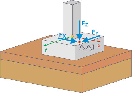
In RFEM 6, additional foundation loads allow for precise modeling of real loading scenarios for foundations. When defining foundation loads, you can select different load types that can be used for various load situations.
In addition to the option to manually define earth coverings and ground water as additional foundation loads, RFEM 6 also provides an automated option.
Earth Covering
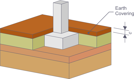
This load type represents a uniform earth covering of the foundation with a user-defined material, such as gravel or sand.
The soil type and thickness of the earth covering are defined in the "Soil Properties" tab of the foundation settings. These values are then included directly in the earth covering design.
When selecting the "Earth Covering" load type for a new additional foundation load, the weight of the soil and the thickness of the earth covering are taken into account. All you have to do is to assign the earth covering to one or more foundations and a load case. This feature uses the information about the position, shape, and cross-sectional area of the column on the foundation, and takes it into account when calculating the earth covering.
Step-By-Step Instructions for Manual Input
- Editing the foundation: Open the "Edit Foundation" dialog box and select the "Soil Properties" tab.
- Creating material: In the "Soil Properties" tab, select a new material for the "Soil Layer on Foundation Plate" from the material library under the "Soil" material type. The density can be adjusted manually, if necessary.
- Defining thickness: Enter the thickness of the earth covering c. Use the visualization in the window to directly check the input.
- Creating an additional foundation load: You can enter the additional foundation loads in the Data navigator under "Loads" and the desired load case at the top of the command bar, or below in the table under "Loads".
- Defining the load type: In the "Edit Additional Foundation Load" dialog box, define the "Earth Covering" load type.
- Assigning the earth covering: Assign the additional foundation load to the corresponding load case and the desired foundations.
In addition to defining the earth covering load manually, RFEM 6 provides the option to consider this load automatically. To do this, select the "Self-weight of foundations" check box in the "Self-Weight" section of the "Load Cases and Combinations" dialog box, the "Load Cases" tab.
A new tab appears where you can activate the earth covering. The earth covering load is automatically calculated and integrated into the loading, based on the soil parameters defined in the foundation (for example, a soil type and thickness of the earth covering).
Ground Water
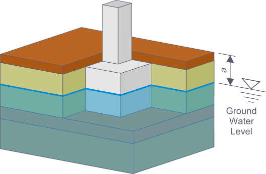
This load type considers the groundwater pressure as an additional load on the foundation. It is particularly relevant for the foundations lying below the ground water level, as there is a buoyancy effect on the foundation. The groundwater pressure is applied below the foundation as an upwards-acting area load, which enables the realistic simulation of buoyancy and soil-related loads.
To define the groundwater level, you must activate the "Ground Water" option in the "Soil Properties" tab and specify the depth of the groundwater level relative to the surface of the foundation plate. These values are then included in the calculation of loads.
Step-by-Step Instructions for Manual Input
- Editing the foundation: Open the "Edit Foundation" dialog box and select the "Soil Properties" tab.
- Activating groundwater: Activate the "Ground Water" option by selecting the check box.
- Defining the groundwater level: Define the depth of the groundwater level dGWL relative to the top side of the foundation plate.
- Creating an additional foundation load: You can enter the additional foundation loads in the Data navigator under "Loads" and the desired load case at the top of the command bar, or below in the table under "Loads".
- Defining the load type: In the "Edit Additional Foundation Load" dialog box, define the "Ground Water" load type.
- Assignment to the foundations: Assign the new load to one or more foundations and to a load case.
You can also use an automated option to consider the groundwater pressure. To do this, select the "Self-Weight of Foundations" check box in the "Load Cases" tab of the "Load Cases and Combinations" dialog box.
A new tab appears where you can activate the groundwater. The groundwater pressure is automatically applied as a load below the foundation that takes into account the buoyancy; it is based on the depth of the groundwater level defined in the foundation.
Surface Load
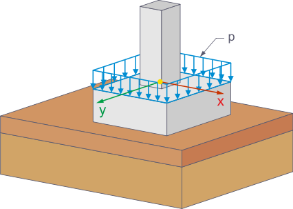
This load type allows you to define an area load on the foundation manually. This feature is especially useful for internal column foundations that are loaded over their entire surface, except for the surface for the column.
Step-by-Step Instructions
- Creating an additional foundation load: You can enter the additional foundation loads in the Data navigator under "Loads" and the desired load case at the top of the command bar, or below in the table under "Loads".
- Selecting the load type: Select the "Area Load" type in the "Additional Foundation Load" dialog box.
- Defining the load size: Define the desired value of the area load in the "Additional Foundation Load" dialog box.
- Assigning the surface load: Assign the additional foundation load to the corresponding load case and the desired foundations.
Line Load
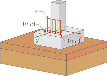
The "Line Load" type is used when a load acts on the foundation along a line, such as in the case of narrow racks. This type of loading provides a realistic representation of longitudinal loads that cause specific stressing of the foundation.
Step-by-Step Instructions
- Creating an additional foundation load: You can enter the additional foundation loads in the Data navigator under "Loads" and the desired load case at the top of the command bar, or below in the table under "Loads".
- Selecting the load type: Select the "Line Load" type in the "Additional Foundation Load" dialog box.
- Defining the load size: Enter the desired value of the line load p.
- Defining line coordinates: Enter the coordinates (x1, y1) and (x2, y2) between which the line load should act.
- Assignment: Assign the line load to the corresponding load case and the desired foundations.
Concentrated Load
The "Concentrated Load" type is ideal for modeling concentrated loads that stress the foundation locally. Such loads often occur in the case of partially covered foundations, where the foundation is only selectively loaded by a floor slab, or the shape of the loaded surface is not covered by the load types described above.
Step-by-Step Instructions
- Creating an additional foundation load: You can enter the additional foundation loads in the Data navigator under "Loads" and the desired load case at the top of the command bar, or below in the table under "Loads".
- Selecting the load type: In the "Additional Foundation Load" dialog box, define the "Concentrated Load" type.
- Defining force components: Enter the value of the load components Fx, Fy, and Fz.
- Defining eccentricities: Specify the eccentricities ex and ey to determine the exact position of the concentrated load on the foundation.
- Assignment: Assign the concentrated load to the corresponding load case and the desired foundations.

