In the Construction Stages Analysis (CSA) add-on, you can use built-up cross-sections by means of what are known as phase sections. Parts of a cross-section of the type "Parametric - Massive II" can be activated or deactivated gradually throughout the construction stages.
Phase Sections in Construction Stages Analysis (CSA) Add-on
Do you have any questions?
![KB 001825 | WebService & API for Analysis of Construction Stages](/en/webimage/043728/3590317/pic_01-en.png?mw=512&hash=9652f38462e139ce7f4d8252eec22adc0c61c803)
When calculating regular structures, data input is often not complicated but time-consuming. Input automation can save valuable time. The task described in the present article is to consider the stories of a house as single construction stages. Data is entered using a C# program so that the user does not have to enter the elements of the individual floors manually.
![Global Deformations for Entire Model](/en/webimage/030251/3278769/2_EN.png?mw=512&hash=8a6981b36c375db03247d20825dc80df4ca9124b)
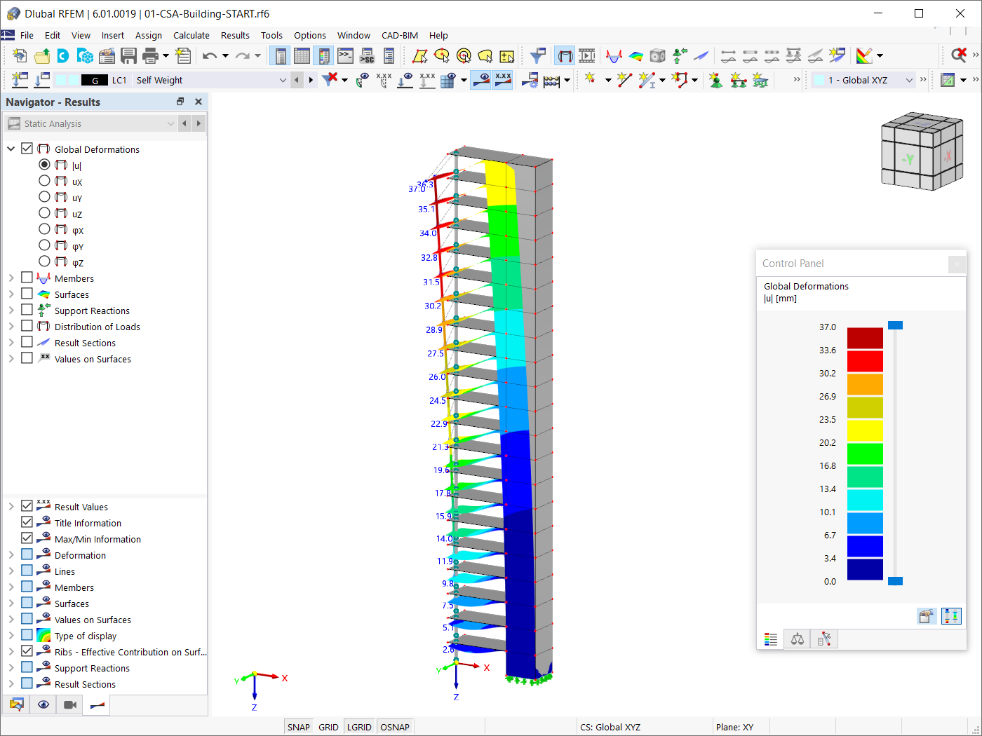
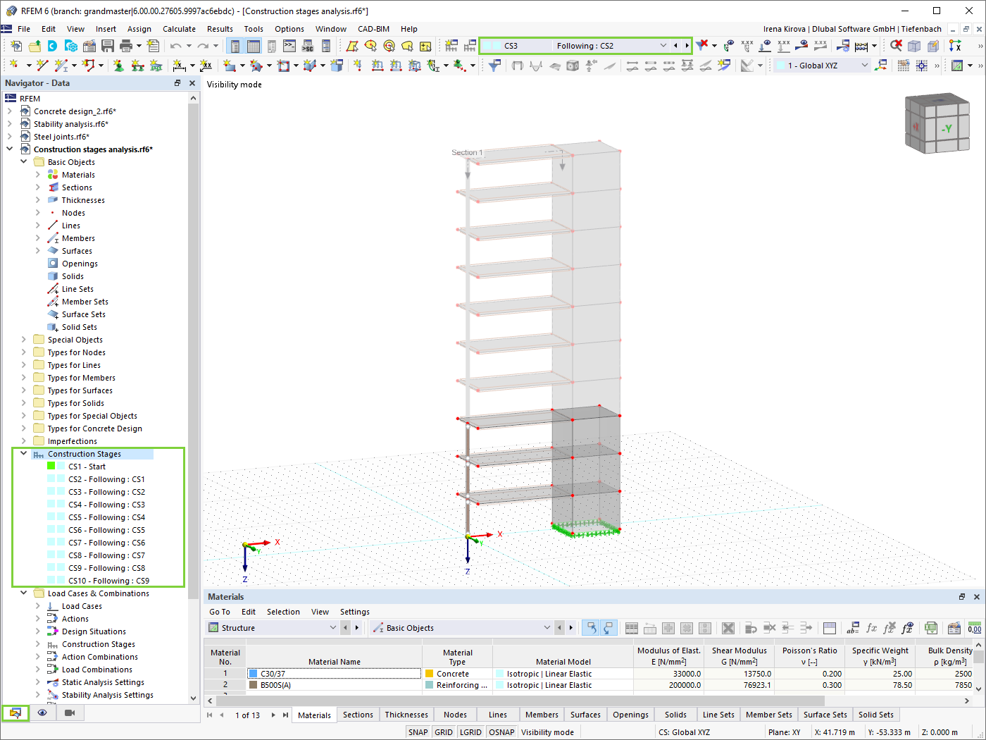
The Construction Stages Analysis (CSA) add-on allows for the design of member, surface, and solid structures in RFEM 6 considering the specific construction stages associated with the construction process. This is important since buildings are not constructed all at once, but by gradually combining individual structural parts. The single steps in which structural elements, as well as loads, are added to the building are called construction stages, whereas the process itself is called a construction process.
Thus, the final state of the structure is available upon completion of the construction process; that is, all the construction stages. For some structures, the influence of the construction process (that is, all the individual construction stages) might be significant and it should be considered so that errors in the calculation are avoided. A general overview of the CSA add-on is given in the Knowledge Base article titled “Consideration of Construction Stages in RFEM 6”.
![Construction Stages in RFEM 6](/en/webimage/026130/3182044/1._Construction_Stages.png?mw=512&hash=bc4b40db376f830a5be0a7d113fa3604599f9767)
The calculation of complex structures by means of finite element analysis software is generally performed on the entire model. However, the construction of such structures is a process carried out in multiple stages where the final state of the building is achieved by combining the separate structural parts. To avoid errors in the calculation of overall models, the influence of the construction process must be considered. In RFEM 6, this is possible using the Construction Stages Analysis (CSA) add-on.
![KB 001883 | Plate Girder Design According to AISC 360-22 in RFEM 6](/en/webimage/051561/3980997/im1.png?mw=512&hash=b8237709c4f30213fac51d86d32a42bddde72f03)
Plate girder is an economical choice for long spans construction. I-section steel plate girder typically has a deep web to maximize its shear capacity and flange separation, yet thin web to minimize the self-weight. Due to its large height-to-thickness (h/tw) ratio, transverse stiffeners may be required to stiffen the slender web.
![Add-on "Steel Joints for RFEM 6" | Component Library](/en/webimage/043097/3898884/steel_joints_components.png?mw=512&hash=e4f835906155863fc7019d5043b22e553dc766f9)
- Numerous component types, such as base and end plates, web angles, fin plates, gusset plates, stiffeners, tapers, or ribs for easy input of typical connection situations
- Universally applicable basic components (such as plates, welds, bolts, auxiliary planes) for modeling complex connection situations
- Graphical display of the connection geometry with dynamic updating during the input
- Wide range of cross-section shapes: I-sections, U-sections, angles, T-sections, hollow sections, built-up cross-sections and thin-walled sections
- Library in the Dlubal Center with a large number of program-side template connections, including user-defined templates
- Automatic adaptation of the connection geometry based on the relative arrangement of the components to each other – even in case of subsequent editing of the structural components
![Feature 002840 | Graphical Add-on Result Display by Design Situation](/en/webimage/051593/3982947/Bemessungssituation.png?mw=512&hash=7fd0d9a61cbc8d701205795390d25dfae3caa76b)
In the Navigator – Results, you can select the design situations for which you want to display the add-on results graphically.
![Feature 002843 | Dimensioning with Result Function](/en/webimage/051576/3982510/1.png?mw=512&hash=9d7f6c198b6d4ae6ee8f2fa8bca75f85579e14c9)
For design objects, you can optionally display sags or extreme results.
![Feature 002844 | Dynamic Shadows](/en/webimage/051588/3982928/Schatten.png?mw=512&hash=4630ba5c10dbeb16f7d0f764f7f67b758275979d)
You can add dynamic shadows in the rendering mode. In the shortcut menu, you can use sliders to change the main light position.