
Wind Simulation model of the Magnolia, RWIND Simulation demo model.
Overall
This page has 0 user ratings.
| 5 star | ||
| 4 star | ||
| 3 star | ||
| 2 star | ||
| 1 star |

Duration: 00:02:15 min

Duration: 00:29:07 min

Duration: 00:45:33 min

Duration: 00:02:38 min

Duration: 01:03:43 min

Duration: 00:02:31 min

Duration: 00:02:19 min

Duration: 00:00:09 min

Duration: 00:00:51 min


.png?mw=512&hash=71474bbf484eff50cf2eb4da2f7c0a5d6103a65d)
This article provides an overview of RFEM 6 and RSTAB 9's dynamic analysis capabilities, highlighting essential add-ons and learning resources for seismic analysis, vibration-resistant design, and structural dynamics applications.
.png?mw=512&hash=4a84cbc5b1eacf1afb4217e8e43c5cb50ed8d827)
This article provides a comprehensive overview of essential seismic analysis methods, explaining their principles and applications, as well as the scenarios in which they are most effective

The Structure Stability add-on is a useful tool when analyzing structural components susceptible to buckling. Using the example of a tapered cantilever beam, the determination of the failure mode and the branching load is shown.

In this article, we will explore the various types of stability failures, delving into their key features, causes, and how they manifest in different structural systems.


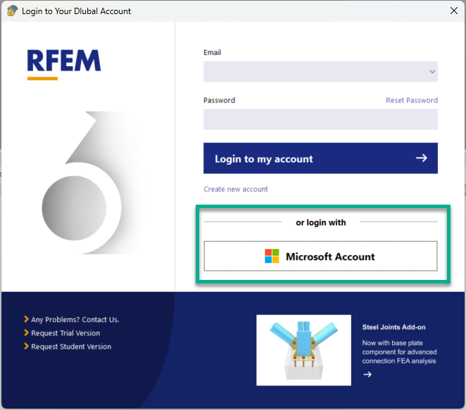
In addition to the program login using your Dlubal account, you can optionally log in with your Microsoft account.
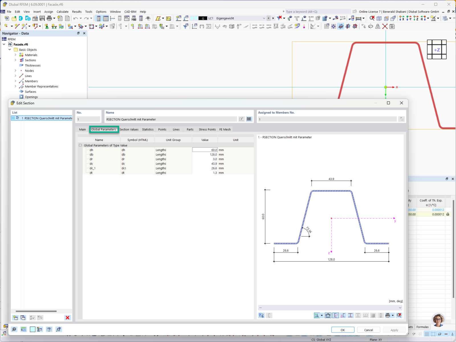
In RFEM and RSTAB, you can use parametric RSECTION cross-sections. If the corresponding parameters have been defined in RSECTION, you can easily modify them in RFEM/RSTAB.

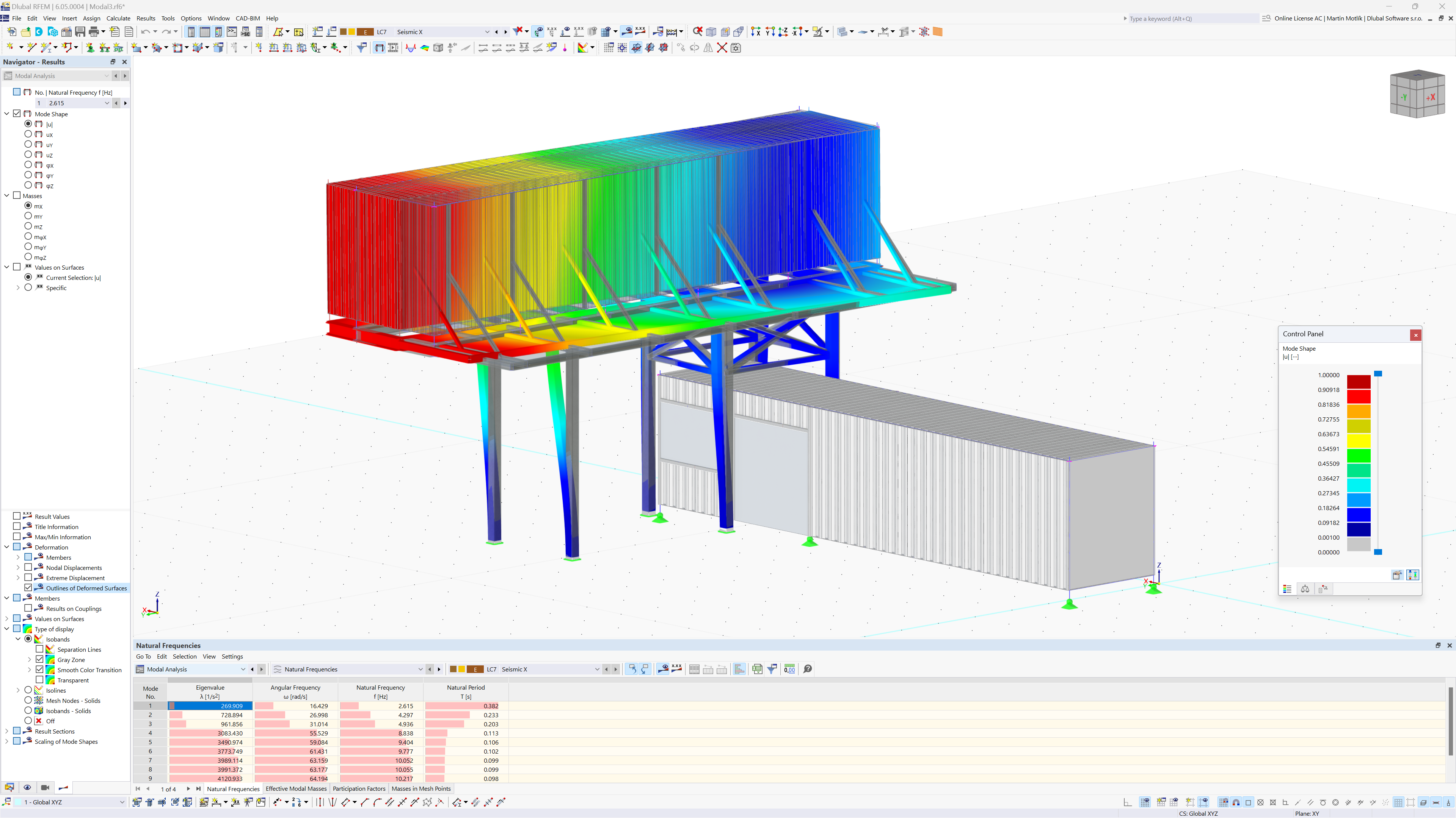
With the new implemented Caculation Diagram Monitor, nodal result diagrams can now be shown and animated (over time or over Load step).
The Calculation Diagram Monitor can be open while still having access to the program itself.

In RFEM and RSTAB, you can display interactive comments, including object properties for objects, such as members, surfaces, and so on. The comments can be moved or hidden at any time.
How can I merge a set of members or multiple members into a single member?
How does single sign-on work with RFEM 6?
Is it possible to test the API II without incurring costs?
Where can I set the fator for deformation display factor for graphical printout, for example, in the printout report?
Is it possible to consider shear panels and rotational restraints in the global calculation?
For my NVIDIA graphics card, I need to select between a driver from the "Production Branch" and a "New Feature Branch." Which driver is best suited for RFEM/RSTAB?


Recommended Products for You
RFEM 6 | Main Program RFEM 6

The new generation of 3D FEA software is used for the structural analysis of members, surfaces, and solids.
Price of First License
4,790.00 USD
RFEM 6 | Additional Analysis

The Form-Finding add-on finds the optimal shape of members subjected to axial forces and tension-loaded surface models. The shape is determined by the equilibrium between the member axial force or the membrane stress and the existing boundary conditions.
Price of First License
2,320.00 USD