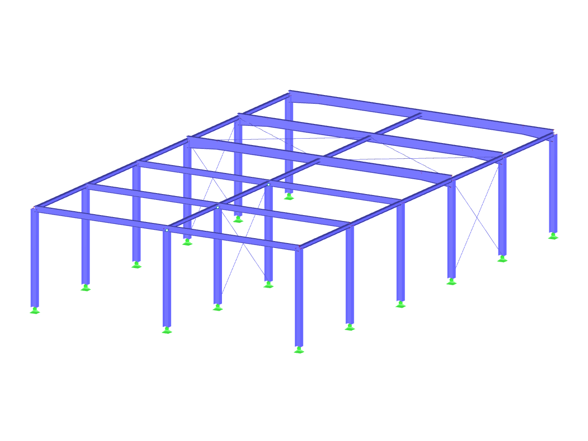
The arched hall has a 72 ft x177 ft rectangular floor plan, a height of 33 ft, and a 66 ft roof radius.
Hall with Steel Arched Roof
No Download Possible
Customer Project / View Only
Number of Nodes | 1242 |
Number of Lines | 1943 |
Number of Members | 1943 |
Number of Load Cases | 1 |
Total Weight | 74.063 tons |
Dimensions (Metric) | 21.472 x 24.788 x 9.987 m |
Dimensions (Imperial) | 70.45 x 81.33 x 32.77 feet |
Program Version | 5.24.01 |
Related Models
![Shear Area of Parametric Rolled Section IPE 300](/en/webimage/010192/3041305/1_shear_area_from_parametric_hot_rolled_section_IPE_300.png?mw=512&hash=0a97ccd9a730aac009d9e73fa0b33fe0154dc3ff)
Cross-section properties in RFEM and RSTAB include different types of shear areas. This technical article explains the calculation and meaning of various values.
![Activating Weld Design in RF-/STEEL EC3](/en/webimage/010282/3040103/1_activate_weld_design.png?mw=512&hash=9fb5bd77c9e682432b746c03fecdba8aa80b4678)
The RF‑/STEEL EC3 add-on module can perform the design of fillet welds for all parametric, welded cross-sections of the cross-section library. For this, the option must be activated in the detail settings of the module. As an alternative, you can also use a surface model for the design.
![Smallest Magnification Factor for Flexural Buckling in Frame Plane](/en/webimage/010280/2993348/1_mode_shape_in_plane_buckling.png?mw=512&hash=3ae4b5e831c1025605c328fda1a888e0a3d36055)
In EN 1993-1-1, the General Method was introduced as a design format for stability analyses that can be applied to planar systems with arbitrary boundary conditions and variable structural height. The design checks can be performed for loading in the main load-bearing plane and simultaneous compression. The stability cases of lateral-torsional buckling and flexural buckling are analyzed from the main supporting plane; that is, about the weak component axis. Therefore, the issue often arises as to how to design, in this context, flexural buckling in the main load-bearing plane.
![Switch Option in Design Details](/en/webimage/010344/2992651/1_Activate_Automatic_Switch_to_General_Method.png?mw=512&hash=4deb9611952f056ff42e89ada3274387f42d24e1)
For the stability design of members and sets of members with a uniform cross-section, you can use the equivalent member method according to EN 1993-1-1, 6.3.1 to 6.3.3. However, as soon as a tapered cross-section is available, this method can no longer be used, or only used to a limited extent. The RF-/STEEL EC3 add-on module can automatically recognize these cases and switch to the general method.
![Add-on "Steel Joints for RFEM 6" | Component Library](/en/webimage/043097/3898884/steel_joints_components.png?mw=512&hash=e4f835906155863fc7019d5043b22e553dc766f9)
- Numerous component types, such as base and end plates, web angles, fin plates, gusset plates, stiffeners, tapers, or ribs for easy input of typical connection situations
- Universally applicable basic components (such as plates, welds, bolts, auxiliary planes) for modeling complex connection situations
- Graphical display of the connection geometry with dynamic updating during the input
- Wide range of cross-section shapes: I-sections, U-sections, angles, T-sections, hollow sections, built-up cross-sections and thin-walled sections
- Library in the Dlubal Center with a large number of program-side template connections, including user-defined templates
- Automatic adaptation of the connection geometry based on the relative arrangement of the components to each other – even in case of subsequent editing of the structural components
![Feature 002820 | Limit Plastic Strain for Welds](/en/webimage/050344/3881226/1.png?mw=512&hash=9d7f6c198b6d4ae6ee8f2fa8bca75f85579e14c9)
In the ultimate configuration of the steel joint design, you have the option to modify the limit plastic strain for welds.
![Component "Base Plate"](/en/webimage/050345/3936120/50345.png?mw=512&hash=3bd641cb1a2445804b338855e4debfc40c6563e9)
The "Base Plate" component allows you to design base plate connections with cast-in anchors. In this case, plates, welds, anchorages, and steel-concrete interaction are analyzed.
![Feature 002807 | 3D Display of FSM Results](/en/webimage/049281/3861162/2024-05-01_10-32-55.png?mw=512&hash=2377d291bc20ac3d78d617b50c131614e99ac6f7)
In the "Edit Section" dialog box, you can display the buckling shapes of the Finite Strip Method (FSM) as a 3D graphic.
What could be the reason?
Recommended Products for You