Do you have any questions about Dlubal products or need assistance in selecting the right one for your project?
I'm here to help. You can easily reach me through the contact options provided below.
Looking forward to hearing from you!
Amy Heilig, PE
CEO – USA Subsidiary | Sales Engineer

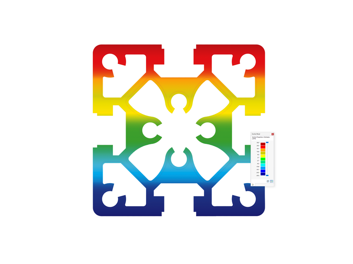
Software for Aluminum and Lightweight Structures
Questions about this topic? Mia answers immediately!


.png?mw=1024&hash=aeb4eef06592d784fa1f0dfcb514e59fd45bcb79)
.png?mw=1024&hash=57381b3403d64cbfff746d4ec63688173298e8de)
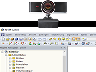
Main Program RFEM or RSTAB


Recommended Add-on Products for Aluminum Structures

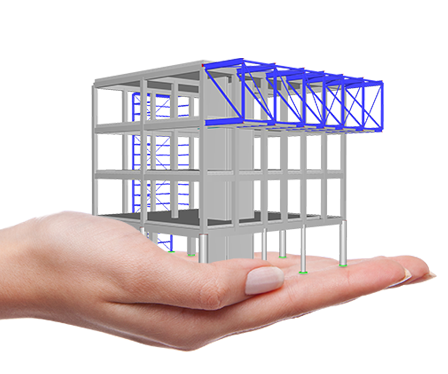

Construction Stages
Construction Stages Analysis (CSA) for RFEM 6
Add-On
The Construction Stages Analysis (CSA) add-on allows for considering the construction process of structures (member, surface, and solid structures) in RFEM.
Support and Learning
We provide professional support and many services in order to help you with finding a quick and efficient solution for your projects.
Great Product and Top Customer Support
Excellent product… even though it's a requirement of some designers, this is one of the few programs on the market that performs the design of aluminum sections. Customer support is top-notch and always ready. I recommend this program!
.JPG?mw=80&hash=674b83d33ba4ba5a808f27abed3617a325c0cc6a)
Ing. Pasquale Ottaviano
Technical Manager, Tiziano Lunardi Srl
Via Paina, 14, 37045, Legnago (VR)
Italy
.png?mw=192&hash=f63e4a3f1836233005de32f60201d5392e507cf1)

NIO User Experience Center in Hefei, China
A new User Experience Center has been added to the well-known NeoPark in Hefei, China. Like the NIO logo, the structure's upper half symbolizes the sky and the lower half the earth – a truly beautiful building.
-
Project Location
Hefei, China
-
Software
RFEM 6
More About Customer Project
© Wenpeng Zhao and Shanghai Cima Engineering Consulting Co., Ltd
_(1).png?mw=1696&hash=63ae5235c9516dd743368b0337e942fec4f92388)

Integrated Standards for Aluminum and Lightweight Structures
Standards for Aluminum Design
Annexes for EN 1999-1-1
My name is Mia: Your 24/7 AI Assistant
Do you have any questions about aluminum structures?
.png?mw=80&hash=24e105a767cf2e175614b729c2d2fa1673e4e81b)
Didn't receive assistance from Mia? Please reach out to our support teams:
Technical Support | Sales Team
Technical Support | Sales Team