

.png?mw=600&hash=74e7e95979c66e5db4329f819ecc3ac2e63545b7)
.png?mw=192&hash=f63e4a3f1836233005de32f60201d5392e507cf1)
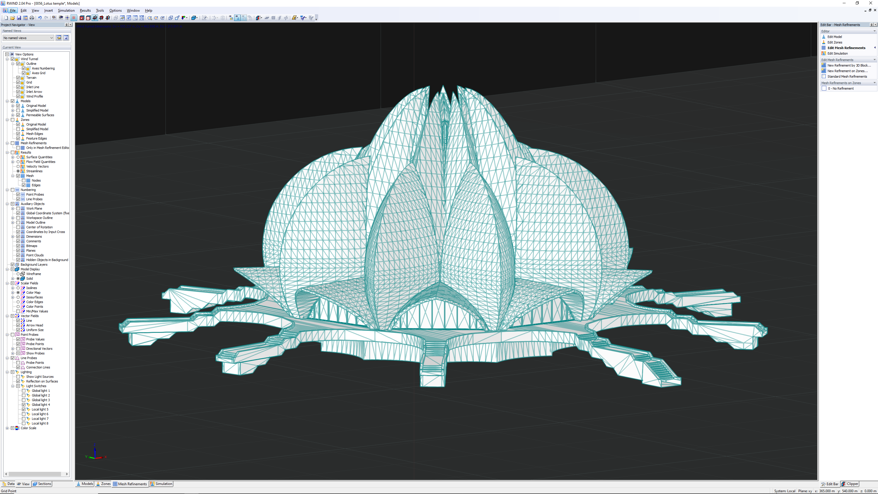
- Verification Example
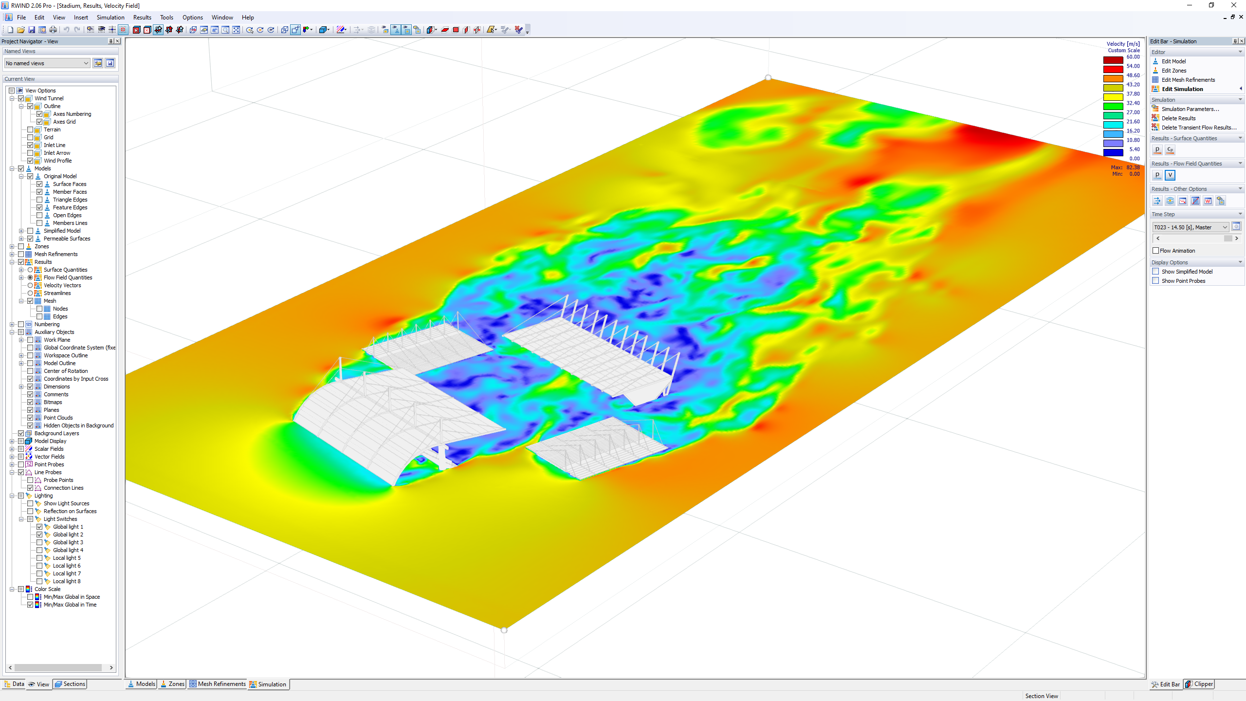
- Wind Tunnel Size
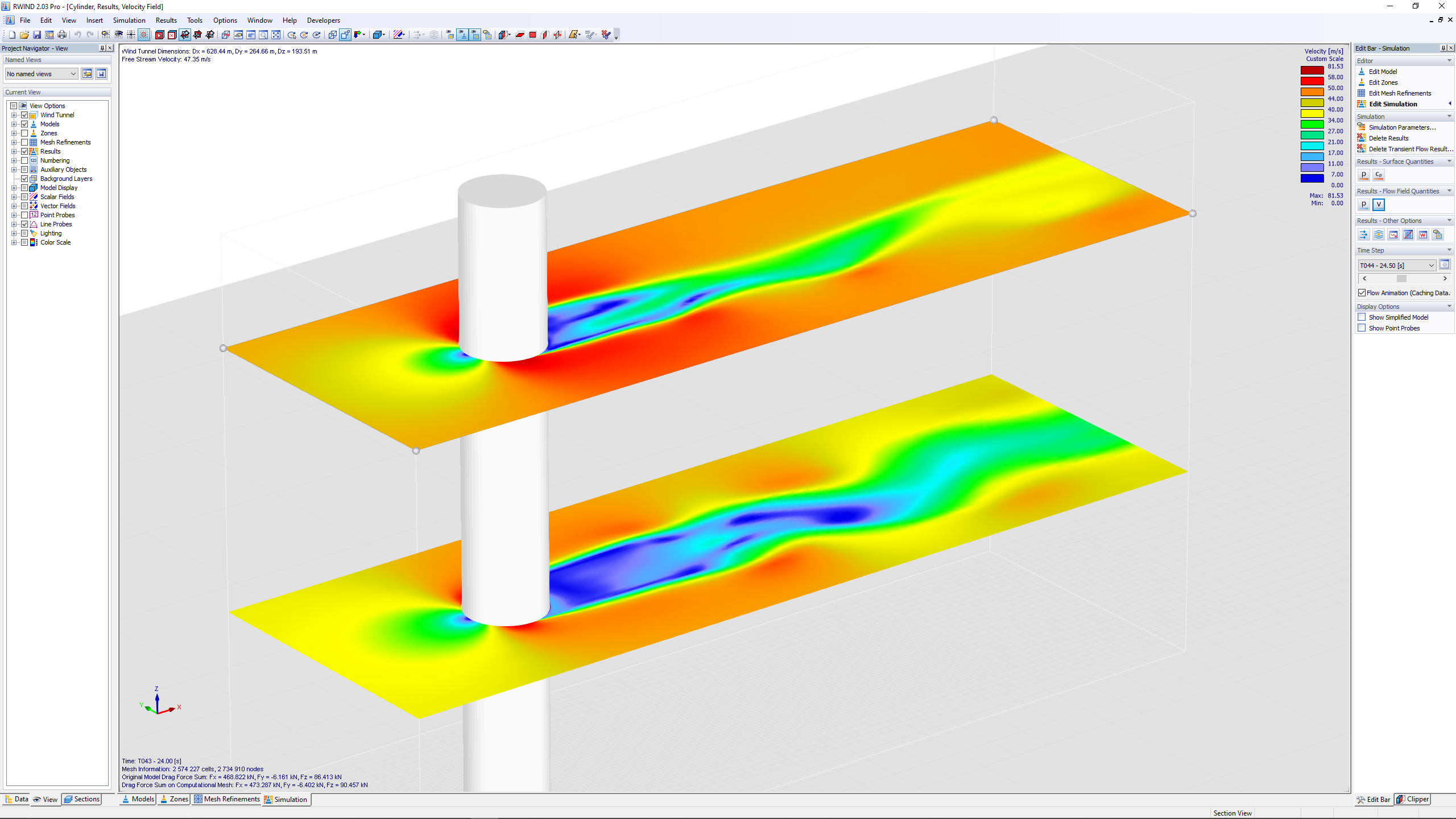
- Computational Grid Study
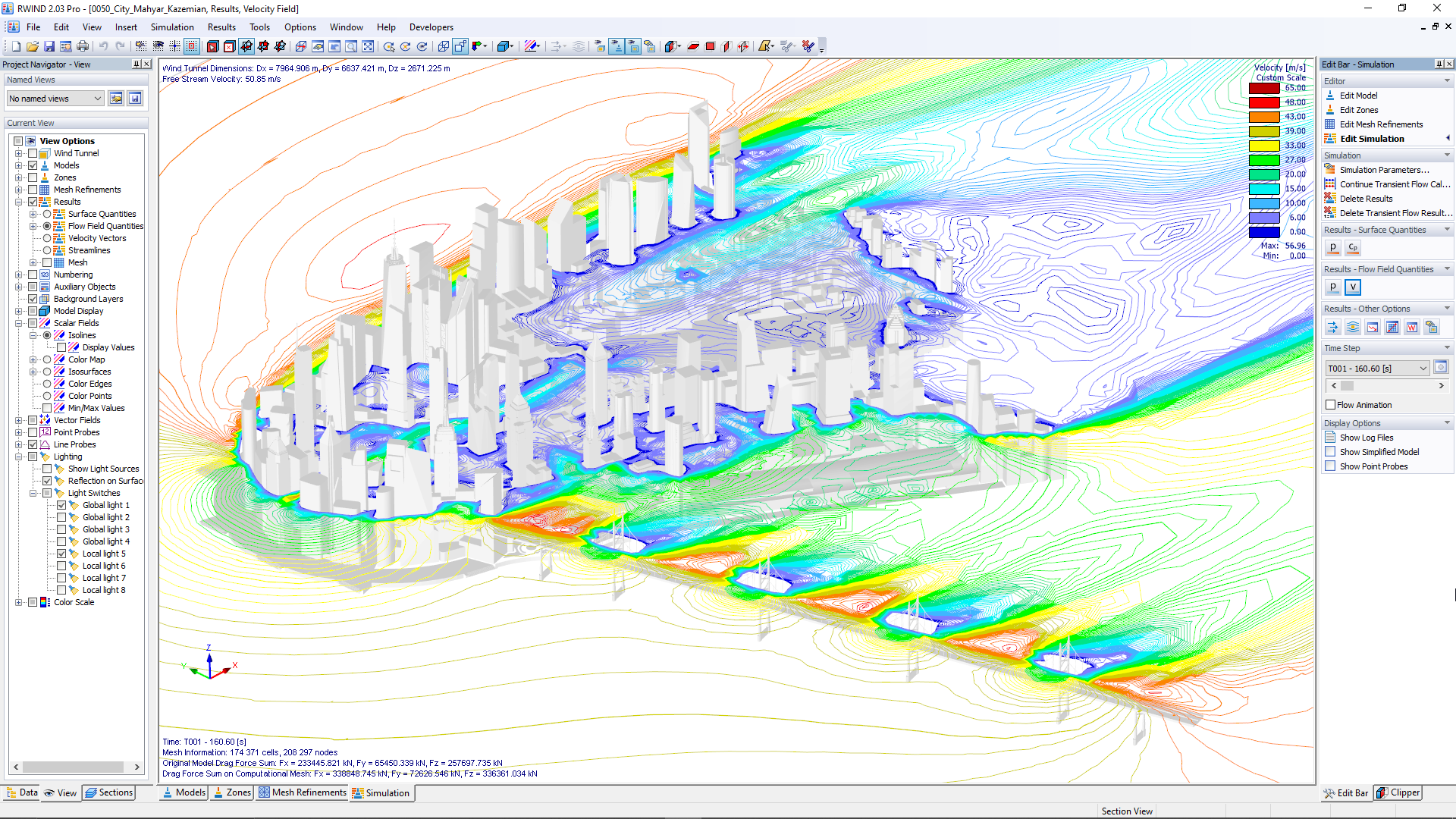
- Enhanced Wall Function
Do you have any questions about Dlubal products or need assistance in selecting the right one for your project?
I'm here to help. You can easily reach me through the contact options provided below.
Looking forward to hearing from you!
 © Kunstlin Ingenieure

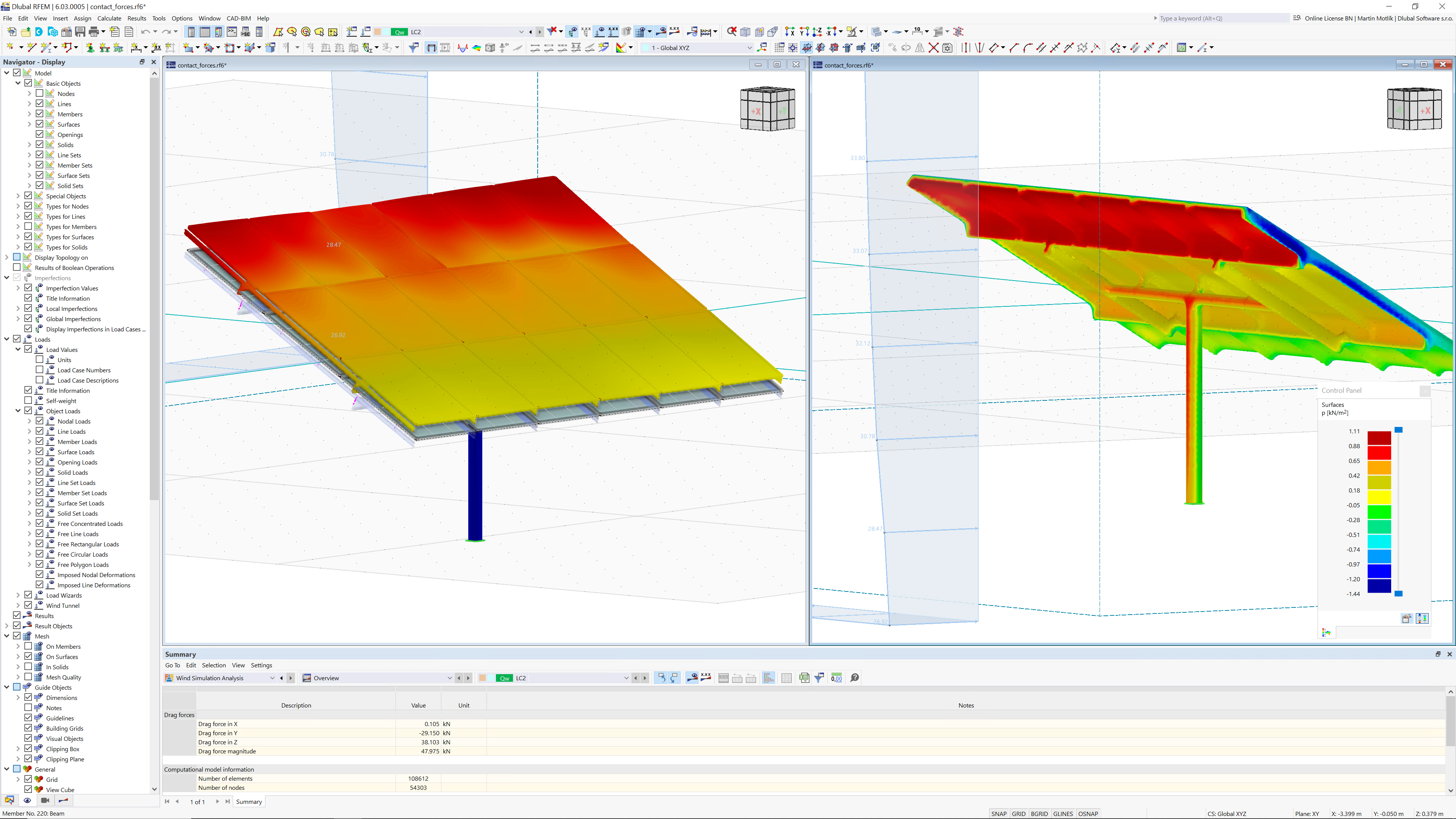
RWIND 3 is used to determine wind loads for buildings. In addition to a 3D model, all you need is a wind load description. The program automatically determines all other parameters for the flow simulation, so the analysis is performed at the push of a button.
RWIND 3 is a stand-alone program, but can also interact with the structural analysis programs RFEM and RSTAB.
The usual workflow includes creating a model in RFEM or RSTAB and then performing the wind analysis in RWIND using a digital wind tunnel. In this case, RWIND can optionally run in the background. The wind loads determined in RWIND are then applied to RFEM and RSTAB.
RWIND is suitable not only for buildings in structural engineering, but for all (including complex) structures.

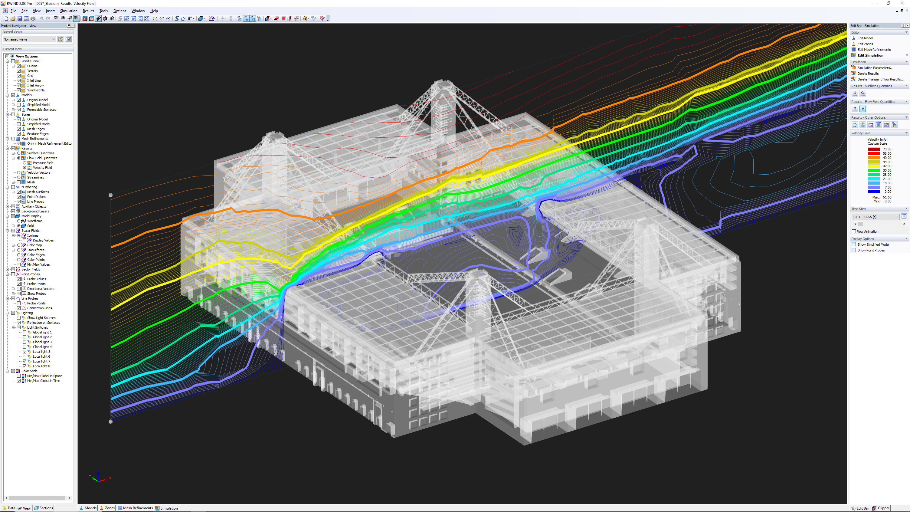
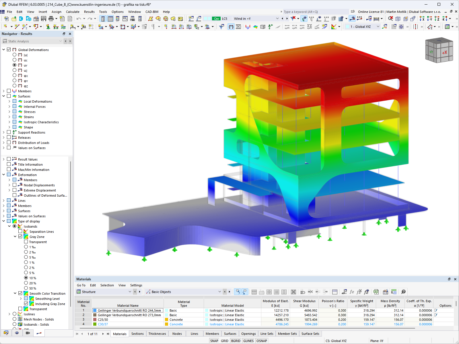
The graphical workspace takes up the main part of the user interface. There you can create the model, apply loads, as well as examine the results. By clicking or rotating the cube (hold down the left mouse key while moving the pointer), you can control the view. As an alternative, you can use the mouse functions to set the view.
The navigator manages the file data in a tree structure. At the bottom edge, there are three tabs (four after the calculation). Use them to switch between the tabs that control the Data, Display, Views, and Results.
The Edit Bar – Simulation guides you through the simulation settings, including the basic control of the individual simulation results. In the window, you can find a result box, a reference to further model changes and the components for editing the results.
The Simulation Parameters dialog boxes guide you through the settings of the wind simulation, for example: Setting of the transient flow behavior or the wind profile.
As in RFEM and RSTAB, the user interface of RWIND is based on the CAD concept. A navigator with an editing window ensures easy navigation and control of the simulations. In the navigator, you can find the functions required for controlling the model display, including the result display. The editing window allows you to control the simulation results, define their properties and run the individual simulations, such as the flow animation, or the display of pressure or wind velocity fields.
Moreover, RWIND provides you with an intuitive user interface, allowing you to easy control and customize your simulations. Dlubal Software is constantly working on updates and improvements of the existing features. The useful features of RWIND include:
The webinar about RWIND Simulation was very successful!
From now on, it is possible to analyze wind forces on geometries of objects that are not regulated in the standard. The wind force assumption according to the standard was often a more or less good estimate.
The RFEM add-on module RF-STABILITY is a perfect combination with RWIND Simulation. Using RF-STABILITY, I can perform a buckling analysis to get accurate effective lengths. Using RWIND Simulation, I can get accurate wind loads. For unusually shaped structures, it would be a wild guess if calculating wind loads from the standard code… either not conservative or too conservative. My client is happy with the results and impressed!
RFEM 6 / RSTAB 9
To model the bodies in RWIND Basic, you will find a special application in RSTAB. In this application, you define the wind directions to be analyzed using related angular positions around the vertical model axis.
RWIND 3
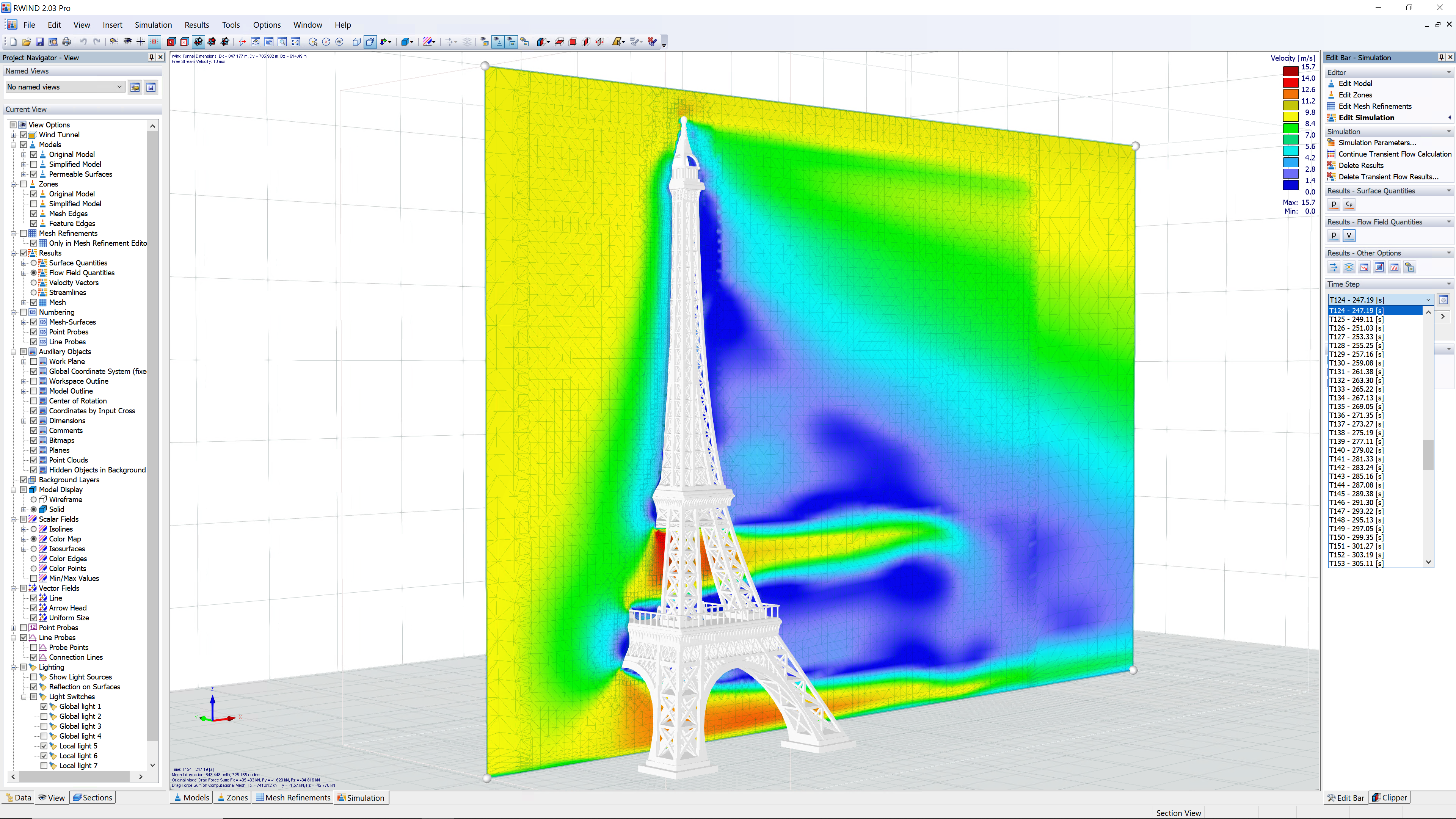
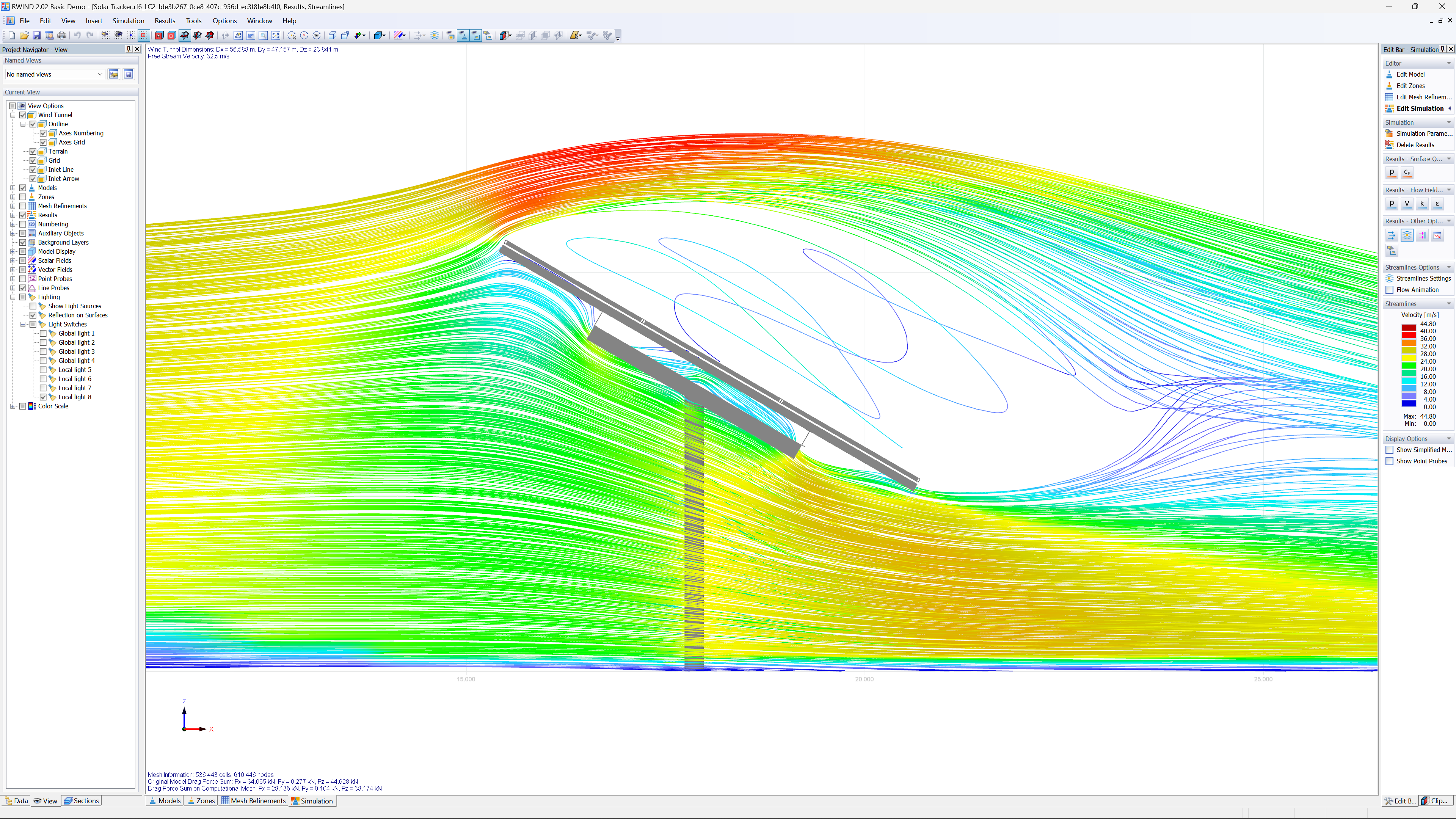
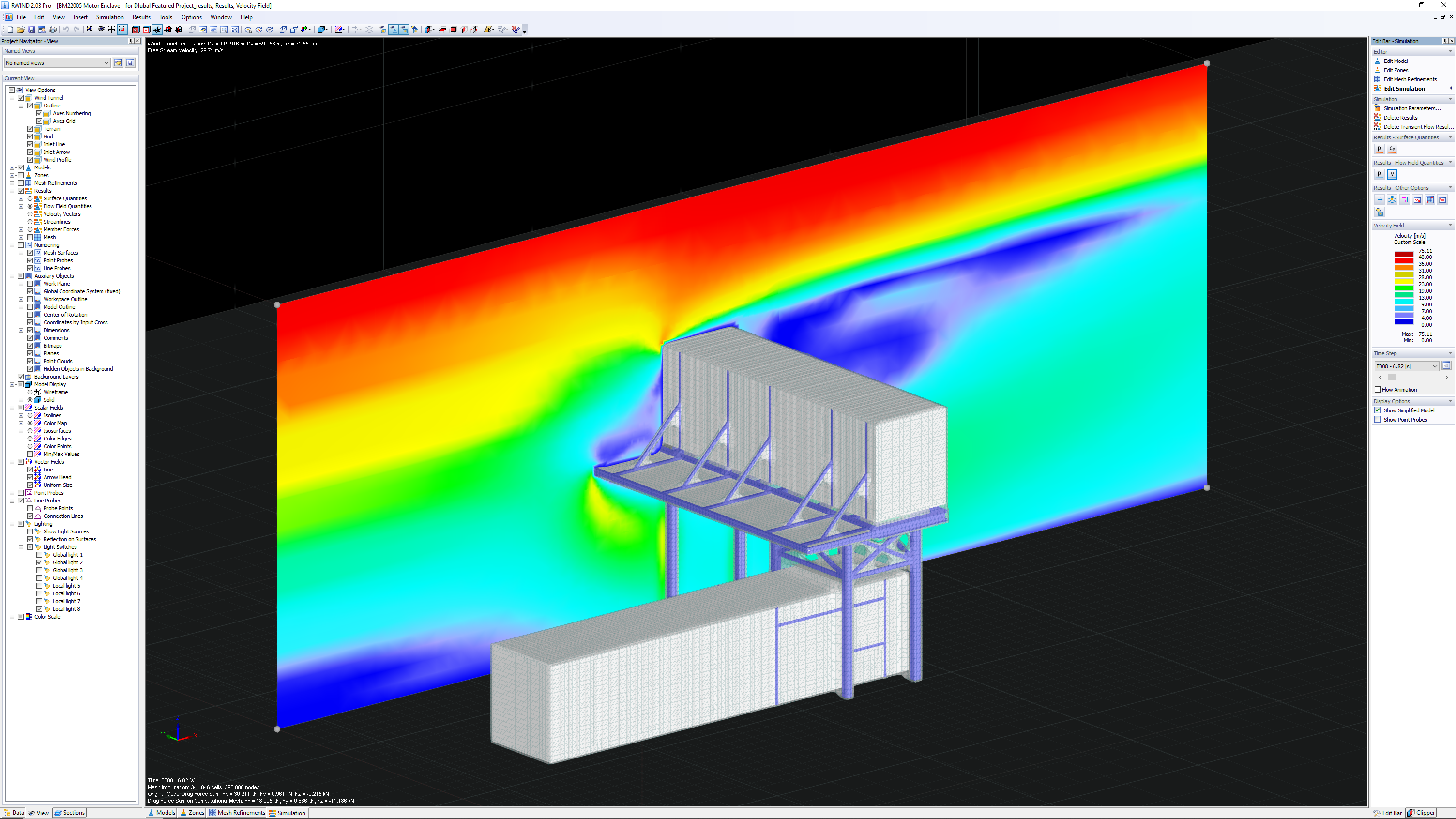
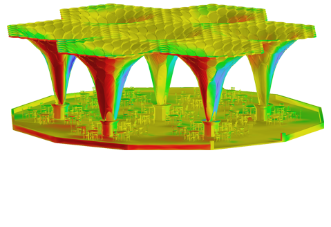
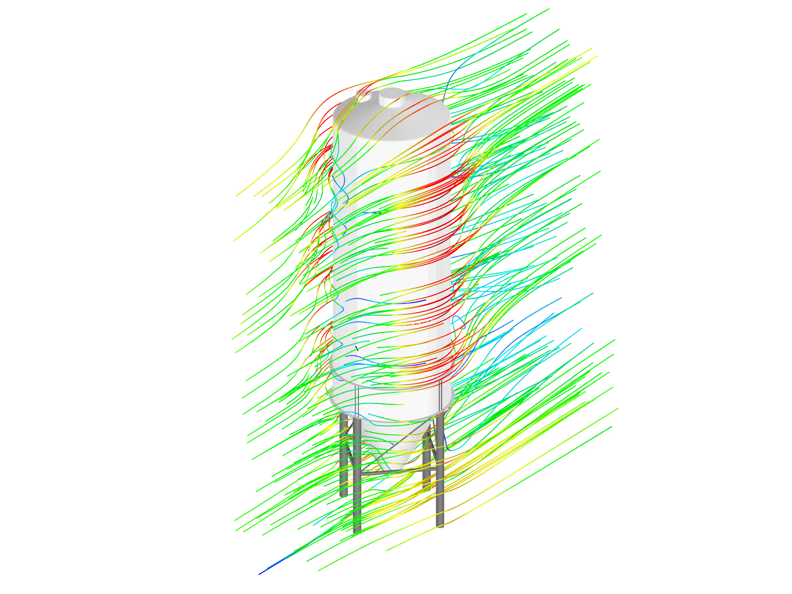
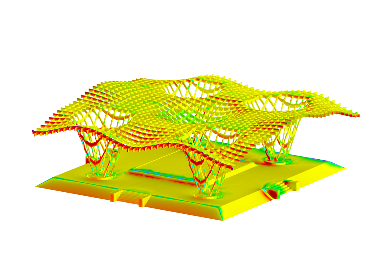
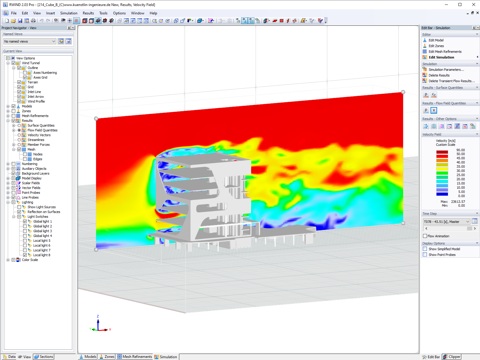
RWIND uses a numerical CFD (Computational Fluid Dynamics) model to simulate wind flows around your objects using a digital wind tunnel.
Use RWIND 2 Pro to easily apply a permeability to a surface. All you need is the definition of the Darcy coefficient D, the inertial coefficient I, and the length of the porous medium in the direction of flow L,to define a pressure boundary condition between the front and back of a porous zone. Due to this setting, you obtain the flow through this zone with a two-part result display on both sides of the zone area.

The price is valid for United States.


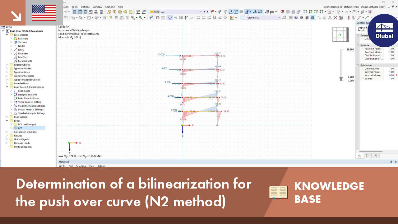
The pushover analysis is managed by a newly introduced analysis type in the load combinations. Here, you have access to the selection of the horizontal load distribution and direction, the selection of a constant load, the selection of the desired response spectrum for the determination of the target displacement, and the pushover analysis settings tailored to the pushover analysis.
In the pushover analysis settings, you can modify the increment of the increasing horizontal load and specify the stopping condition for the analysis. Furthermore, it is possible to easily adjust the precision for the iterative determination of the target displacement.


During the calculation, the selected horizontal load is increased in load steps. A static nonlinear analysis is carried out for each load step until reaching the specified limit condition.
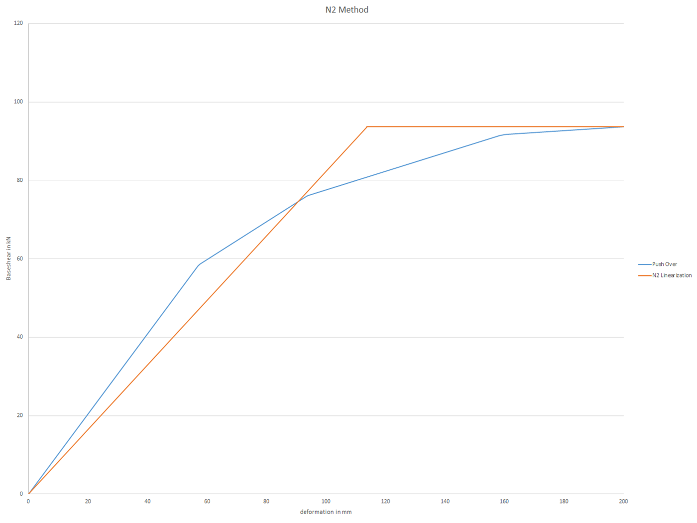
The results of the pushover analysis are extensive. On one hand, the structure is analyzed for its deformation behavior. This can be represented by a force-deformation line of the system (a capacity curve). On the other hand, the response spectrum effect can be displayed in the ADRS display (Acceleration-Displacement Response Spectrum). The target displacement is automatically determined in the program based on these two results. The process can be evaluated graphically and in tables.
The individual acceptance criteria can then be graphically evaluated and assessed (for the next load step of the target displacement, but also for all other load steps). The results of the static analysis are also available for the individual load steps.