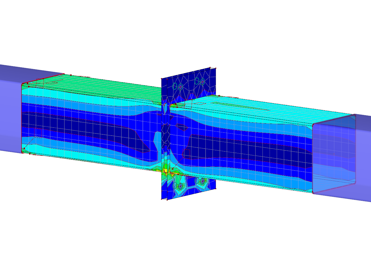
FEA steel connection modeled in RFEM with 3D solid elements. The webinar in the link below demonstrates the workflow when modeling with solids in RFEM.
Steel Connection Modeled with Solid Elements
Number of Nodes | 385 |
Number of Lines | 415 |
Number of Surfaces | 178 |
Number of Solids | 12 |
Number of Load Cases | 3 |
Total Weight | 0.658 tons |
Dimensions (Metric) | 1.458 x 0.982 x 1.687 m |
Dimensions (Imperial) | 4.78 x 3.22 x 5.53 feet |
Program Version | 5.23.01 |
You can download this structural model to use it for training purposes or for your projects. However, we do not assume any guarantee or liability for the accuracy or completeness of the model.
![Problem Background](/en/webimage/008957/575821/01-de.png?mw=512&hash=9f2525444a7414dfb1c05a73e375e9c4fe4f47b1)
![Gas Behavior in Gas Volume](/en/webimage/009278/2417893/01-en-png.png?mw=512&hash=e5b08a40fd9a5a16825be6182b3138f78627561e)
![KB 001883 | Plate Girder Design According to AISC 360-22 in RFEM 6](/en/webimage/051561/3980997/im1.png?mw=512&hash=b8237709c4f30213fac51d86d32a42bddde72f03)
![Steel Connection Rigidity and Its Influence on Structural Design](/en/webimage/051432/3972404/Rigidity-caseA.png?mw=512&hash=3be64e68ab2956fd2b92f0afa1559b3a8c72b468)
![Defining 2 FE Mesh Layers for One Gas Solid](/en/webimage/006847/1585448/1390-en-png.png?mw=512&hash=9d6ea057e28eee373d3f5d28ff89a46ddd98bf8a)
The stiffness of gas given by the ideal gas law pV = nRT can be considered in the nonlinear dynamic analysis.
The calculation of gas is available for accelerograms and time diagrams for both the explicit analysis and the nonlinear implicit Newmark analysis. To determine the gas behavior correctly, at least two FE layers for gas solids should be defined.
![Add-on "Steel Joints for RFEM 6" | Component Library](/en/webimage/043097/3898884/steel_joints_components.png?mw=512&hash=e4f835906155863fc7019d5043b22e553dc766f9)
- Numerous component types, such as base and end plates, web angles, fin plates, gusset plates, stiffeners, tapers, or ribs for easy input of typical connection situations
- Universally applicable basic components (such as plates, welds, bolts, auxiliary planes) for modeling complex connection situations
- Graphical display of the connection geometry with dynamic updating during the input
- Wide range of cross-section shapes: I-sections, U-sections, angles, T-sections, hollow sections, built-up cross-sections and thin-walled sections
- Library in the Dlubal Center with a large number of program-side template connections, including user-defined templates
- Automatic adaptation of the connection geometry based on the relative arrangement of the components to each other – even in case of subsequent editing of the structural components
![Feature 002820 | Limit Plastic Strain for Welds](/en/webimage/050344/3881226/1.png?mw=512&hash=9d7f6c198b6d4ae6ee8f2fa8bca75f85579e14c9)
In the ultimate configuration of the steel joint design, you have the option to modify the limit plastic strain for welds.
![Component "Base Plate"](/en/webimage/050345/3936120/50345.png?mw=512&hash=3bd641cb1a2445804b338855e4debfc40c6563e9)
The "Base Plate" component allows you to design base plate connections with cast-in anchors. In this case, plates, welds, anchorages, and steel-concrete interaction are analyzed.