Structural System and Loading
A single-span beam with a length of 15 m is given. The cross-section of the single-span beam is an IPE 400 made of S355. The load is 5 kN/m. The self-weight is neglected.
Design Without Stabilization
The design can be carried out with the standard settings (single-span beam with lateral and torsional restraints) of the RF‑/STEEL EC3 add-on module according to the German National Annex, and is not fulfilled.
The critical buckling moment is only 72.61 kNm here, and this value is confirmed by common formulas from technical literature.
Design with Stabilization on Upper Chord
The displacement of the upper chord is fixed by means of a virtual transverse bar, connecting at the middle of the upper chord.
This stabilization can be performed in RF‑/STEEL EC3 by means of a lateral intermediate restraint, without having to divide the member for this purpose.
The subsequent design according to Section 6.3.2.3 of EN 1993‑1‑1 [1] leads to a successful design and a critical buckling moment of 209.52 kNm.
Comparison with General Method as Design of Sets of Members
In the next step, the verification will be performed according to the general method as the design of sets of members. For this purpose, the member can be copied in the Y‑direction, including supports and loading, divided once in the middle, and a set of members can be created.
The set of members is now selected for the design in a new design case in RF‑/STEEL EC3. Instead of Table "1.5 Effective Lengths - Members", Table "1.7 Nodal Support" is displayed. By default, two supports with support φx' and uy' have been defined at the start and end of the set of design brackets.
To stabilize it in the middle, another support has to be created and provided with an eccentricity of -200 mm in the local z‑direction.
The supports can easily be displayed via a button in the partial view window.
The verification is successful and a critical factor of 1.49 is calculated.
By using the maximum moment, the critical buckling moment of 209.54 kNm can be determined, which corresponds to the last calculation.
The slenderness ratio of the beam is given as 1.488 and is required for applying the imperfection in the following section.
Comparison with Warping Analysis
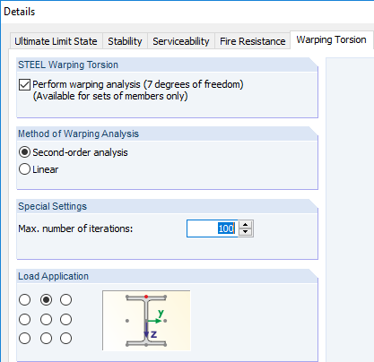
In the next step, the critical factor will be compared to the warping analysis, which means that seven degrees of freedom are used instead of four degrees of freedom.
It is necessary to select the "Perform warping analysis" option in the "Details" dialog box, "Warping Torsion" tab.
As with the method according to 6.3.4 EN 1993‑1‑1, it is necessary to check the nodal supports and, if necessary, adjust them.
An imperfection value of L/400 is given in Window 1.13.
The subsequent design is more favorable and leads to a critical factor of 1.489, which corresponds very well to the previous designs.
Comparison with RF-/FE-LTB Add-on Module
In the last step, the single-span beam (set of members) will be designed with the RF‑/FE‑LTB add-on module, and the critical factor will be compared again here.
In RF‑/FE‑LTB, the nodal supports defined at the set of members are directly imported.
However, it is impossible to define an eccentricity, which is why the intermediate restraint is not defined as a nodal support, but as a member end spring in Window 1.6.
When entering the load, pay attention to applying the eccentricity, since an overly favorable calculation takes place otherwise.
The imperfection is manually set to 1.875 cm for the first mode shape.
The final calculation results in a critical factor of 1.489 and corresponds to all previous calculations.


