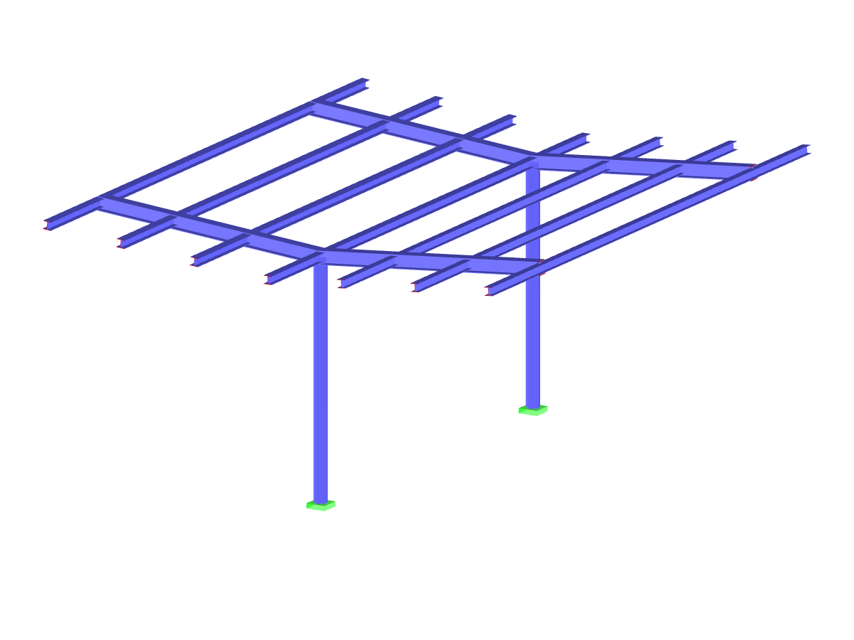
The timber structure of the school’s entrance is a half glued-laminated timber frame. Web plate connections were used between the posts and the rafters. In the upper section, the rafters are supported at one end on a concrete wall.
The timber posts are hinged to the concrete floor and the frames run between each post.
A longitudinal beam further supports the roof purlins.
BMB-BET Moselle Bois, Saint Julien Lès Metz, France
www.bet-moselle-bois.fr
RFEM model of the frame in the day school (© BET Moselle Bois)
The timber posts are hinged to the concrete floor and the frames run between each post.
A longitudinal beam further supports the roof purlins.
BMB-BET Moselle Bois, Saint Julien Lès Metz, France
www.bet-moselle-bois.fr
RFEM model of the frame in the day school (© BET Moselle Bois)
Submodels
Roof Structure
No Download Possible
Customer Project / View Only
Number of Nodes | 77 |
Number of Lines | 147 |
Number of Members | 147 |
Number of Load Cases | 4 |
Number of Load Combinations | 21 |
Number of Result Combinations | 4 |
Total Weight | 4.111 tons |
Dimensions (Metric) | 15.000 x 7.494 x 3.425 m |
Dimensions (Imperial) | 49.21 x 24.59 x 11.24 feet |
Program Version | 5.23.02 |
Related Models
![Activating Weld Design in RF-/STEEL EC3](/en/webimage/010282/3040103/1_activate_weld_design.png?mw=512&hash=9fb5bd77c9e682432b746c03fecdba8aa80b4678)
The RF‑/STEEL EC3 add-on module can perform the design of fillet welds for all parametric, welded cross-sections of the cross-section library. For this, the option must be activated in the detail settings of the module. As an alternative, you can also use a surface model for the design.
![Smallest Magnification Factor for Flexural Buckling in Frame Plane](/en/webimage/010280/2993348/1_mode_shape_in_plane_buckling.png?mw=512&hash=3ae4b5e831c1025605c328fda1a888e0a3d36055)
In EN 1993-1-1, the General Method was introduced as a design format for stability analyses that can be applied to planar systems with arbitrary boundary conditions and variable structural height. The design checks can be performed for loading in the main load-bearing plane and simultaneous compression. The stability cases of lateral-torsional buckling and flexural buckling are analyzed from the main supporting plane; that is, about the weak component axis. Therefore, the issue often arises as to how to design, in this context, flexural buckling in the main load-bearing plane.
![Switch Option in Design Details](/en/webimage/010344/2992651/1_Activate_Automatic_Switch_to_General_Method.png?mw=512&hash=4deb9611952f056ff42e89ada3274387f42d24e1)
For the stability design of members and sets of members with a uniform cross-section, you can use the equivalent member method according to EN 1993-1-1, 6.3.1 to 6.3.3. However, as soon as a tapered cross-section is available, this method can no longer be used, or only used to a limited extent. The RF-/STEEL EC3 add-on module can automatically recognize these cases and switch to the general method.
![Flexural Buckling Lines According to EN 1993-1-1](/en/webimage/010469/2987565/1_Knicklinien.png?mw=512&hash=9ad9ab1e9a7ae48f1bdadef46d94aff35c70c44c)
The RF‑/STEEL EC3 add-on module automatically transfers the buckling line to be used for the flexural buckling analysis for a cross-section from the cross-section properties. The assignment of the buckling line can be adjusted manually in the module input for general cross-sections in particular, as well as for special cases.
![Feature 002820 | Limit Plastic Strain for Welds](/en/webimage/050344/3881226/1.png?mw=512&hash=9d7f6c198b6d4ae6ee8f2fa8bca75f85579e14c9)
In the ultimate configuration of the steel joint design, you have the option to modify the limit plastic strain for welds.
![Component "Base Plate"](/en/webimage/050345/3936120/50345.png?mw=512&hash=3bd641cb1a2445804b338855e4debfc40c6563e9)
The "Base Plate" component allows you to design base plate connections with cast-in anchors. In this case, plates, welds, anchorages, and steel-concrete interaction are analyzed.
![Feature 002807 | 3D Display of FSM Results](/en/webimage/049281/3861162/2024-05-01_10-32-55.png?mw=512&hash=2377d291bc20ac3d78d617b50c131614e99ac6f7)
In the "Edit Section" dialog box, you can display the buckling shapes of the Finite Strip Method (FSM) as a 3D graphic.
![Steel Design | Seismic Force-Resisting System Design Overview](/en/webimage/048507/3803346/seismic_steel.png?mw=512&hash=1c18a83f050e74601a7300444a0d77a0246a0e02)
- Design of five types of seismic force-resisting systems (SFRS) includes Special Moment Frame (SMF), Intermediate Moment Frame (IMF), Ordinary Moment Frame (OMF), Ordinary Concentrically Braced Frame (OCBF), and Special Concentrically Braced Frame (SCBF)
- Ductility check of the width-to thickness ratios for webs and flanges
- Calculation of the required strength and stiffness for stability bracing of beams
- Calculation of the maximum spacing for stability bracing of beams
- Calculation of the required strength at hinge locations for stability bracing of beams
- Calculation of the column required strength with the option to neglect all bending moments, shear, and torsion for overstrength limit state
- Design check of column and brace slenderness ratios
What could be the reason?
Recommended Products for You