Download the model of a castellated beam with circular holes as a surface model here, and open it with the finite element analysis software RFEM.
This model is available in the free webinar "How to Be More Productive Using RFEM". [*S14348397*] [*S14348398*]
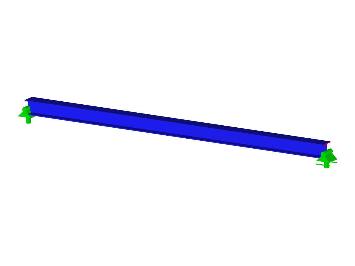
Castellated Beam with Circular Holes as Surface Model
Number of Nodes | 41 |
Number of Lines | 26 |
Number of Members | 1 |
Number of Surfaces | 5 |
Number of Solids | 0 |
Number of Load Cases | 1 |
Number of Load Combinations | 0 |
Number of Result Combinations | 0 |
Total Weight | 1.097 tons |
Dimensions (Metric) | 10.000 x 0.581 x 0.220 m |
Dimensions (Imperial) | 32.81 x 1.91 x 0.72 feet |
You can download this structural model to use it for training purposes or for your projects. However, we do not assume any guarantee or liability for the accuracy or completeness of the model.
![Hall Frame as Basis for Surface Model](/en/webimage/009068/527278/01-en.png?mw=512&hash=65e98cfe859ce35a3e3e9da47a0ef9335401520e)
![Structural System and Cross-Section Dimensions According to [1]](/en/webimage/009153/2417271/01-en-png.png?mw=512&hash=e5b08a40fd9a5a16825be6182b3138f78627561e)
![KB 001883 | Plate Girder Design According to AISC 360-22 in RFEM 6](/en/webimage/051561/3980997/im1.png?mw=512&hash=b8237709c4f30213fac51d86d32a42bddde72f03)
![Steel Connection Rigidity and Its Influence on Structural Design](/en/webimage/051432/3972404/Rigidity-caseA.png?mw=512&hash=3be64e68ab2956fd2b92f0afa1559b3a8c72b468)
![Activation of Camera Flight Mode in RFEM](/en/webimage/007231/1773731/Kamera-Flugmodus.png?mw=512&hash=bfe40bd5994b64cf3b32c3ec1894bde55d8396b8)
With the Camera Fly Mode view option, you can fly through your RFEM and RSTAB structure. Control the direction and speed of the flight with your keyboard. Additionally, you can save the flight through your structure as a video.
![Defining Load Eccentricity for Uniform Member Load](/en/webimage/006848/1585470/1-en-us-png.png?mw=512&hash=5b100bb1bdececb35d942f4f843827e0bc899c6f)
You can define eccentricities for member loads of the load type 'Force'. You can apply the load eccentricities by means of an absolute or relative offset.
We recommend using the large deformation analysis to consider all effects of eccentric loads.
![Add-on "Steel Joints for RFEM 6" | Component Library](/en/webimage/043097/3898884/steel_joints_components.png?mw=512&hash=e4f835906155863fc7019d5043b22e553dc766f9)
- Numerous component types, such as base and end plates, web angles, fin plates, gusset plates, stiffeners, tapers, or ribs for easy input of typical connection situations
- Universally applicable basic components (such as plates, welds, bolts, auxiliary planes) for modeling complex connection situations
- Graphical display of the connection geometry with dynamic updating during the input
- Wide range of cross-section shapes: I-sections, U-sections, angles, T-sections, hollow sections, built-up cross-sections and thin-walled sections
- Library in the Dlubal Center with a large number of program-side template connections, including user-defined templates
- Automatic adaptation of the connection geometry based on the relative arrangement of the components to each other – even in case of subsequent editing of the structural components
![Feature 002820 | Limit Plastic Strain for Welds](/en/webimage/050344/3881226/1.png?mw=512&hash=9d7f6c198b6d4ae6ee8f2fa8bca75f85579e14c9)
In the ultimate configuration of the steel joint design, you have the option to modify the limit plastic strain for welds.