Assumptions for Manual Calculation
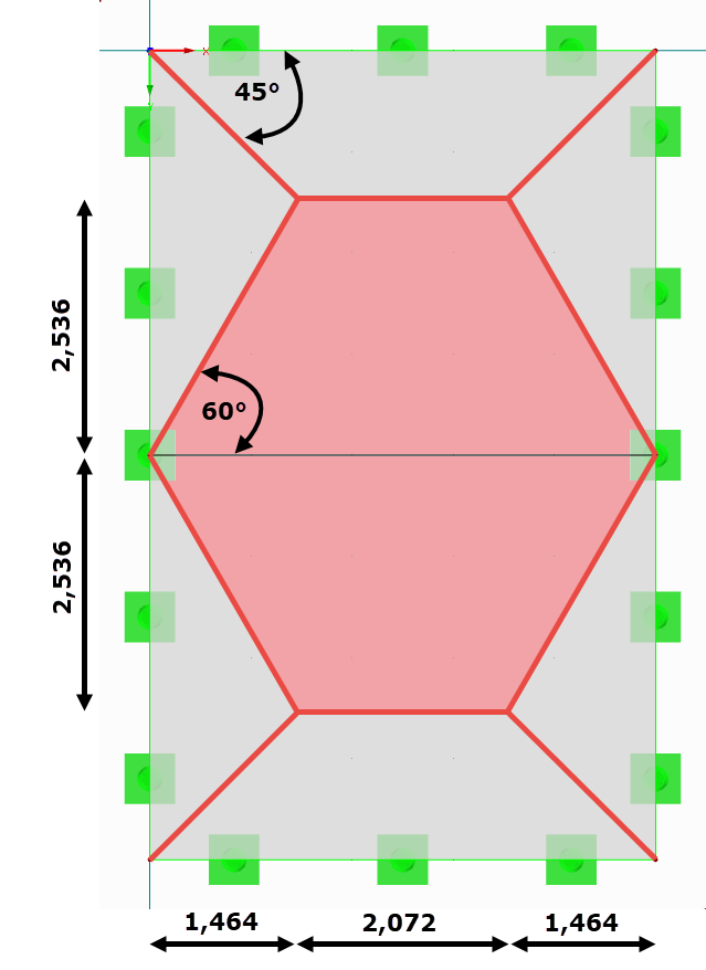
In the manual calculation models, the triangular or trapezoidal member loads of the downstand beams are determined by means of load application areas and tables. It is only distinguished how the plate connects to the respective (boundary) line. If the plate is continuous, it is considered a restraint on the line. If the plate ends at this line, it is a hinged connection. The inclination of the load distribution is 45° at the point of intersection of two perpendicular lines with the same connection property (hinged or rigid). If the lines are perpendicular to each other and have different connection properties, the inclination of the division line is 60°. The line with the restraint receives a greater load due to the higher stiffness. Semi-rigid supports can be considered with an angle between 45° and 60°. If the opposing parallel line is far enough from the considered line, the result is a triangular load. However, if the distance of the opposite line is rather small, the result is a trapezoidal load.
This approach is independent of the member stiffness. This means that the assumed loading remains the same for both a small and a large downstand beam. Moreover, the shear connection between plate and downstand beam is neglected, and the load transfer by the plate is completely neglected. In addition, the favorable effect of the eccentricity is not taken into account.
Calculation Example of a Downstand Beam
A 20-centimeter-thick plate with hinged supports on all sides with dimensions of 5 m by 8 m will be reinforced in the center by a downstand beam with the cross-section dimensions of 30 cm x 40 cm. The total load of 10 kN/m² is only an example as loading without considering the self-weight.
Manual Calculation According to Schneider Construction Tables
Since the plate runs over the downstand beam, the load application of the member is assumed at an angle of 60°.
The maximum load ordinate of a trapezoidal load results in:
0.634 · 10 kN/m² · 4.00 m = 25.36 kN/m
Since the same boundary conditions are present in both spans, the load must be doubled. The load starts with 0 kN/m at the member start and increases over the length of 0.366 · 4.00 m = 1.464 m to the maximum load ordinate. If the downstand beam is loaded with it, the result is a maximum moment of span with My = 140.38 kNm.
RFEM Calculation
The downstand beam was set eccentrically during the modeling. The top edge of the member is connected to the bottom edge of the surface. All the line supports transfer only vertical forces. To prevent the system from becoming kinematic, a nodal support with a support in the X- and Y-directions and a rotation restraint around Z was additionally set in a node. The loading was assumed as a surface load with 10 kN/m².
The result is My = 16.77 kNm.
However, it has to be mentioned here that in addition to the bending moment, a normal force distribution with max N = 254.48 kN results affine to the moment distribution. This results from the fact that the loading is not only transferred by means of bending, but also by a force pair (compression in the plate, tension in the member). In mid-span, it reaches the maximum value and decreases in a parabolic direction towards the edge.
If a reinforced concrete design is carried out for both members, the single member requires a bottom span reinforcement of 10.13 cm², whereas the "real" downstand beam requires only 3.98 cm².
To verify the manual calculation, the combined structure was copied and a rigid member was used instead of the actual cross-section dimensions. In this system, a maximum bending moment of 141.69 kNm is obtained, which corresponds relatively precisely to the manual calculation (140.38). The normal force can be neglected with 0.01 kN.
Conclusion
For very stiff downstand beams or to determine support forces for rigidly fixed supports in the vertical direction, the manual calculation provides consistent results for the FEA calculation. However, FEA programs should be used for more accurate and economical results. In addition to the overestimation of the member internal forces described above, it is similar with the plate internal forces. For example, in the case of a minor beam, it may happen that, instead of the assumed support reinforcement with the FEA program, a positive moment will still occur due to the larger deformation. Instead of the applied support reinforcement (at the top side of the plate), a span reinforcement (at the bottom side of the plate) would have to be arranged when considering the realistic stiffnesses.


