
根据文章{%于#请参阅[1]]],稳定性验算和相关数值示例的几何线性结构分析被视为第一种分析方法。 下面阐述该结构的按照二阶分析方法的力学计算。
此种方法首先将结构弹性临界屈曲模型的形状作为全局和局部缺陷进行引入。 之后考虑等效缺陷,包括初始侧移缺陷 (φ) 和杆件的单个杆件弯曲缺陷 (e)。 最后,以与 [2] 中相同的方式对结果进行分析和评估。
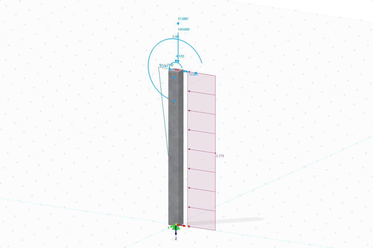
如前所述,现在将这些不同的方法应用到一个数值示例中,并进行检查和比较。 这里的例子是钢框架结构,如图 02 所示。 图中还显示了结构上的作用,以及梁和柱上的作用。

2
钢框架
1.按照几何线性分析的对理想结构进行结构分析
该规范中 EN 1993-1-1:2005 中 5.2.2 (3)c) 中给出的方法{%!根据 6.3 节验算等效杆件的稳定性验算和缺陷分析 [1] 。 为此必须根据欧式屈曲曲线的强度格式和折减系数 xy1 ,根据结构的整体屈曲模式使用合适的屈曲长度。
为此,请确保在 RFEM 6 中同时激活“钢结构设计”模块和“结构稳定性”模块。 这将允许进行稳定性验算并从稳定性分析中导入有效长度(图03)。 更多关于这个主题的信息可以在知识库文章中找到:
在 RFEM 6 中计算有效长度
.

3
定义有效长度
请注意,如果要根据几何线性分析进行结构分析,则必须在要计算的荷载工况和组合中设置分析类型为“几何线性”(图04)。 这样,在计算内力时不考虑缺陷和二阶效应,而是在稳定性分析中通过全局框架行为对屈曲长度系数进行考虑。

4
静力分析设置
使用这种方法在模块“钢结构设计”中得到的结果如图 05 所示。

5
钢结构设计结果
在 RFEM 6 中,屈曲折减系数 x1是按照欧洲屈曲曲线的强度格式计算的。 这可以在各杆件的设计验算详细信息中看到(图06),可以在“钢结构设计结果”表中点击“设计验算详细信息”按钮显示。

2. 二阶分析与几何缺陷的考虑
通常,临界荷载系数小于 10,这意味着在计算内力和弯矩时应考虑二阶效应。 此外,还应考虑几何缺陷,本文采用以下方法:
2.1.应用结构的弹性临界屈曲形状作为全局和局部唯一缺陷
根据 5.3.2.11 [1] 中介绍的方法,结构的弹性临界屈曲形状可以作为一个唯一的全局和局部缺陷来应用。 为此在 RFEM 6 中必须先创建一个缺陷类型为“屈曲模态”的缺陷工况。
结构的第一屈曲振型已经在上一章稳定性分析中计算得出,现在可以用于定义缺陷工况,如图07所示。 二阶分析中缺陷影响的二阶分析设置如图 08 所示。


2.2.考虑等效初始缺陷(φ)和杆件整体初始缺陷(e)
根据5.3.2 (3)中介绍的方法{%于#参考文献 [1]]],在框架分析中应考虑缺陷的影响等效的初始缺陷和单个杆件的弯曲缺陷。
2.2.1.初始侧移缺陷 (φ)
首先,该分析仅考虑初始缺陷形式的等效缺陷。 在 RFEM 6 中,如图 09 所示,作为“杆件集缺陷”引入了全局初始侧移缺陷。

如图 10所示,初始侧移基本确定。

10
初始侧移
2.2.2.初始侧移缺陷 (φ) 和杆件整体初始缺陷 (±e)
除了整体缺陷外,还应考虑杆件相对初始的局部拱形缺陷。 在 RFEM 6 中可将其定义为“初弯曲”类型的杆件缺陷。 在本例中分别在全局 X 正方向 (+e) 和负方向 (-e) 考虑此类缺陷。 如图11和图12所示。


结果摘要
通过对不同方法的比较(图 13)可以得出的结论是,与直接设计方法(方法 2)相比,使用欧式屈曲曲线的强度格式和折减系数1 (方法 1)得出的结果不够保守,它考虑了缺陷和根据二阶效应理论的结构分析。 结果还表明,对于矩形连续框架,考虑方法 2(即 5.3.2(3) 和 5.3.2(11))中的缺陷影响,两种方法的差异很小。

13
不同方法的结果
在这一点上,我们可以参见 EN 1993-1-1:2005 中的 5.3.2 (6) {%!按照 6.3 节计算杆件验算的端部压力和端部弯矩。
因此,在该数值示例中只能作为整体缺陷引入,并且可以按照 6.3 [1] 进行等效杆件的稳定性验算。 [1]。 最终的计算结果如图 14 所示。


..png?mw=320&hash=bd2e7071b02d74aef6228d22c4b83867d2d7e1a5)


_1.jpg?mw=350&hash=ab2086621f4e50c8c8fb8f3c211a22bc246e0552)


-querkraft-hertha-hurnaus.jpg?mw=350&hash=3306957537863c7a7dc17160e2ced5806b35a7fb)


