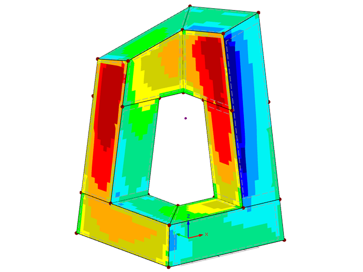
The model explains the relation between RWIND Simulation (CFD wind simulation) and RFEM.
Submodels
Model Used in
Wind Action on PV Tracker System
Number of Nodes | 287 |
Number of Lines | 383 |
Number of Members | 338 |
Number of Surfaces | 18 |
Number of Solids | 0 |
Number of Load Cases | 2 |
Number of Load Combinations | 0 |
Number of Result Combinations | 0 |
Total Weight | 2.300 tons |
Dimensions (Metric) | 10,200 x 5,390 x 5,246 m |
Dimensions (Imperial) | 33.46 x 17.68 x 17.21 feet |
You can download this structural model to use it for training purposes or for your projects. However, we do not assume any guarantee or liability for the accuracy or completeness of the model.
Related Models
2210x
90x
1623x
70x
Computer technology has a firm grip on digital structural analysis and design. With each new development, the planners involved are able to increase the limits of what is feasible.
![Building Model in Various BIM Applications and IFC Viewer and Calculated Model in RFEM (Deformations, Bottom)](/en/webimage/008599/2220847/01-de.jpg?mw=512&hash=6a936175e1cb20b598b1a0f34fee8828d790a343)
The building and construction industry is increasingly digitized. Structural engineers, a smaller group in the construction industry, are not always considered to be engineers who follow the latest trends immediately. There is often good reason for this. Many consider this to be the reason that topics such as utilizing the BIM method are not yet the standard in structural engineering. However, the past few years have shown that a process of rethinking has begun, and new digital trends are being picked up and applied.
Buildings are structures surrounded by wind. The flow around them creates specific loads on the surfaces, which are to be used for the design in structural analysis.
![Model and Computational Domain](/en/webimage/008680/1649185/01-en.png?mw=512&hash=65e98cfe859ce35a3e3e9da47a0ef9335401520e)
The following study compares the wind pressure on a tall building obtained by RWIND Simulation with the results published by Dagnew et al. at the 11th Americas Conference on Wind Engineering in June, 2009. In this paper, the Commonwealth Advisory Aeronautical Council (CAARC) building is used as a model, and the results of several different numerical methods are compared with experimental data obtained from wind tunnels.
![Add-on "Steel Joints for RFEM 6" | Component Library](/en/webimage/043097/3898884/steel_joints_components.png?mw=512&hash=e4f835906155863fc7019d5043b22e553dc766f9)
- Numerous component types, such as base and end plates, web angles, fin plates, gusset plates, stiffeners, tapers, or ribs for easy input of typical connection situations
- Universally applicable basic components (such as plates, welds, bolts, auxiliary planes) for modeling complex connection situations
- Graphical display of the connection geometry with dynamic updating during the input
- Wide range of cross-section shapes: I-sections, U-sections, angles, T-sections, hollow sections, built-up cross-sections and thin-walled sections
- Library in the Dlubal Center with a large number of program-side template connections, including user-defined templates
- Automatic adaptation of the connection geometry based on the relative arrangement of the components to each other – even in case of subsequent editing of the structural components
![Feature 002820 | Limit Plastic Strain for Welds](/en/webimage/050344/3881226/1.png?mw=512&hash=9d7f6c198b6d4ae6ee8f2fa8bca75f85579e14c9)
In the ultimate configuration of the steel joint design, you have the option to modify the limit plastic strain for welds.
![Component "Base Plate"](/en/webimage/050345/3936120/50345.png?mw=512&hash=3bd641cb1a2445804b338855e4debfc40c6563e9)
The "Base Plate" component allows you to design base plate connections with cast-in anchors. In this case, plates, welds, anchorages, and steel-concrete interaction are analyzed.
![Feature 002807 | 3D Display of FSM Results](/en/webimage/049281/3861162/2024-05-01_10-32-55.png?mw=512&hash=2377d291bc20ac3d78d617b50c131614e99ac6f7)
In the "Edit Section" dialog box, you can display the buckling shapes of the Finite Strip Method (FSM) as a 3D graphic.
Recommended Products for You