.svg?mw=64&hash=343d71fbdf234f1411db2920f2dff33c0dbd6231)

The new headquarters of the Baden farmers' association (BLHV) is unique. The timber structure is protected by a glass facade to counteract graying caused by weather conditions. Although the architects of the Werkgruppe Lahr have sufficient experience in timber construction, the wooden house with the glass cladding has been a "model project" for them.
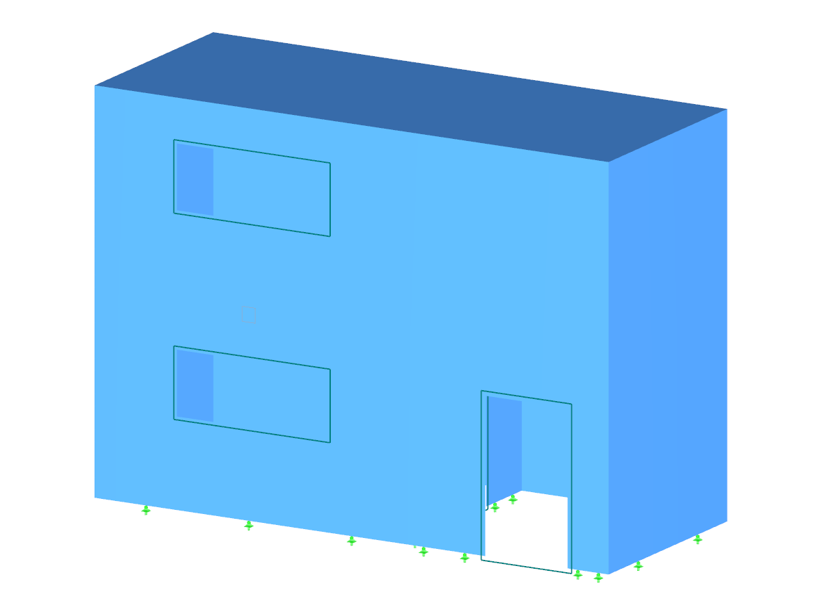
The four-story building offers more than 100 workplaces within a 21,528 ft² office space.
Structural analysis of the solid timber construction was done by a Dlubal Software customer, the engineering office Göppert Bauingenieure from Lahr, Germany.
Göppert Bauingenieure, Lahr, Germany
www.gbi-statik.de
RFEM model of the "House of Farmers" (© Göppert Bauingenieure)
Timber House with Glass Cladding
No Download Possible
Customer Project / View Only
| Number of Nodes | 752 |
| Number of Lines | 1231 |
| Number of Members | 625 |
| Number of Surfaces | 150 |
| Number of Load Cases | 7 |
| Number of Load Combinations | 1 |
| Number of Result Combinations | 1 |
| Total Weight | 4091.251 tons |
| Dimensions (Metric) | 64.915 x 23.285 x 16.700 m |
| Dimensions (Imperial) | 212.98 x 76.39 x 54.79 feet |
| Program Version | 5.02.00 |
Related Models