Analisi della colonna di calcestruzzo
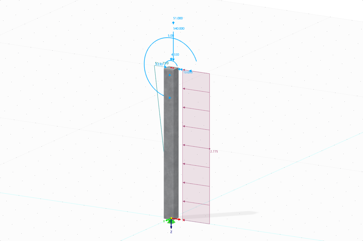
A reinforced square tie concrete column is designed to support axial dead and live loads of 135 and 175 kips, respectively, using ULS design and factored LRFD load combinations according to ACI 318-19 [1] as presented in Image 01. The concrete material has a compressive strength f'c of 4 ksi while the reinforcing steel has a yield strength fy of 60 ksi. The steel reinforcement percentage is initially assumed to be 2%.
Dimension Design
To begin, the dimensions of the cross-section must be calculated. The square tie column is determined to be compression controlled, since all axial loads are strictly in compression. As per Table 21.2.2 [1], the strength reduction factor Φ is equal to 0.65. When determining the maximum axial strength, Table 22.4.2 [1] is referenced, which sets the alpha factor (α) equal to 0.80. Now, the design load Pu can be calculated.
Pu = 1.2 (135) + 1.6 (175) = 442 kips
Based on these factors, Pu is equal to 442 kips. Next, the gross cross-section Ag can be calculated utilizing equation 22.4.2.2.
|
Φ |
Strength reduction factor |
|
α |
Alpha factor |
|
f’c |
Compressive strength |
|
Ast |
Steel reinforcement percentage |
442 kips = (0.65) (0.80) [0.85 (4 kips) (Ag – 0.02 Ag) + ((60 ksi) (0.02) Ag)]
Solving for Ag, we receive an area of 188 in2. The square root of Ag is taken and rounded up to set a cross-section of 14” x 14" for the column.
Required Steel Reinforcement
Now that Ag is established, the steel reinforcement area Ast can be calculated utilizing Eqn. 22.4.2.2 by substituting the known value of Ag = 196 in² and solving it.
442 kips = (0.65) (0.80) [0.85 (4 kips) (196 in² – Ast) + ((60 ksi) (Ast))]
Solving for Ast yields a value of 3.24 in². From this, the number of bars required for design can be found. According to Section 10.7.3.1 [1], a square tie column is required to have at least four bars. Based on these criteria, and the minimum required area of 3.24 in², (8) No. 6 bars for the steel reinforcement are used from Appendix B [1]. This provides the reinforcement area below.
Ast = 3.52 in²
Tie Selection
Determining the minimum tie size requires Section 25.7.2.2 [1]. In the previous section, we selected No. 6 longitudinal bars, which are smaller than No. 10 bars. Based on this information and section, we select No. 3 for the ties.
Tie Spacing
To determine the minimum tie spacing(s), we refer to Section 25.7.2.1 [1]. Ties that consist of closed looped deformed bars must have spacing that is in accordance with (a) and (b) from this section.
(a) The clear spacing must be equal to or greater than (4/3) dagg. For this calculation, we will assume an aggregate diameter (dagg) of 1.00 inches.
smin = (4/3) dagg = (4/3) (1.00 inch) = 1.33 inches
(b) The center-to-center spacing should not exceed the minimum of 16 db of the longitudinal bar diameter, 48 db of the tie bar, or the smallest dimension of the member.
sMax = Min (16 db, 48 db, 14 inches)
16 db = 16 (0.75 inch) = 12 inches
48 db = 48 (0.375 inch) = 18 inches
The minimum clear tie spacing calculated is equal to 1.33 inches and the maximum tie spacing calculated is equal to 12 inches. For this design, a maximum of 12 inches for the tie spacing will govern.
Verifica dettagliata
The detailing check can now be performed to verify the reinforcement percentage. The required steel percentage must be between 1% and 8%, based on the ACI 318-19 [1] requirements, to be adequate.
|
Ast |
Area totale dell'armatura longitudinale non precompressa comprese le barre o i profilati in acciaio ed esclusa l'armatura precompressa |
|
Ag |
Sezione trasversale lorda |
Longitudinal Bar Spacing
The maximum longitudinal bar spacing can be calculated on the basis of the clear cover spacing and the diameter of both the tie and longitudinal bars.
4.00 inches are less than 6 inches, which are required as per 25.7.2.3 (a) [1].
The minimum longitudinal bar spacing can be calculated by referencing 25.2.3 [1], which states that the minimum longitudinal spacing for columns must be at least the greatest of (a) through (c).
(a) 1.5 inches
(b) 1.5 db = 1.5 (0.75 inch) = 1.125 inches
(c) (4/3) db = (4/3) (1.00 inch) = 1.33 inches
Therefore, the minimum longitudinal bar spacing is equal to 1.50 inches.
The development length (Ld) must also be calculated with reference to 25.4.9.2 [1]. This will be equal to the greater of (a) or (b) calculated below.
|
fy |
Specified yield strength for nonprestressed reinforcement |
|
ψr |
Factor used to modify development length based on confining reinforcement |
|
λ |
Modification factor to reflect the reduced mechanical properties of lightweight concrete relative to normal weight concrete of the same compressive strength |
|
f'c |
Compressive strength |
|
db |
Nominal diameter of bar, wire, or prestressing strand |
|
fy |
Specified yield strength for nonprestressed reinforcement |
|
ψr |
Factor used to modify development length based on confining reinforcement |
|
db |
Nominal diameter of bar, wire, or prestressing strand |
In this example, (a) is the greater value, so Ldc = 14.23 inches.
Referencing 25.4.10.1 [1], the development length is multiplied by the ratio of the required steel reinforcement over provided steel reinforcement.
The reinforced square tie column is fully designed, and its cross-section can be viewed below in Image 02.
Comparison with RFEM
An alternative to designing a square tie column manually is utilizing the Concrete Design add-on in RFEM 6 and performing the design as per the ACI 318-19 [1] standard. The add-on will determine the required reinforcement to resist the applied loads on the column. The user is then required to make adjustments manually to the provided reinforcement layout to meet the required reinforcement shown.
Based on the applied loads for this example, RFEM 6 has determined a required longitudinal bar reinforcement area of 3.24 in². The development length calculated in the Concrete Design add-on is equal to 0.81 ft. The discrepancy in comparison to the development length above, calculated with analytical equations, is due to the program's non-linear calculations, including the partial factor γ. The factor γ is the ratio of ultimate and acting internal forces taken from RFEM. The development length in the Concrete Design add-on is found by multiplying the reciprocal value of gamma by the length determined from 25.4.9.2 [1]. This development length and reinforcement can be previewed in Image 03 and Image 04, respectively.
The minimum required shear reinforcement area (Av,min) for the member within the Concrete Design add-on was calculated to be 0.14 in² bars with a minimum spacing (smax) of 12 inches. The required shear reinforcement layout is shown below in Image 05.


..png?mw=320&hash=bd2e7071b02d74aef6228d22c4b83867d2d7e1a5)


,_Table_22.5.5.1_ACI_318-19.png?mw=512&hash=fb0c95268ba55403adf6343e213a103627a3b5e4)


_1.jpg?mw=350&hash=ab2086621f4e50c8c8fb8f3c211a22bc246e0552)


-querkraft-hertha-hurnaus.jpg?mw=350&hash=3306957537863c7a7dc17160e2ced5806b35a7fb)


