Introduzione
Nella norma precedente ACI 318-14 [2], sono state specificate otto equazioni per il calcolo della resistenza a taglio Vc - senza considerare i limiti di applicazione. L'utente può scegliere tra un metodo di calcolo semplificato e uno dettagliato. Uno degli obiettivi del nuovo concetto in ACI 318-19 era quello di ridurre le equazioni di progetto per Vc . Inoltre, il concetto dovrebbe considerare l'influenza dell'altezza del componente, il rapporto di armatura longitudinale e la tensione normale.
Resistenza al taglio Vc secondo ACI 318-19
For non-prestressed reinforced concrete beams, the shear resistance Vc is calculated according to ACI 318-19 [1] with Equations a) to c) from Table 22.5.5.1. With the new Equations b) and c), the member height, the longitudinal reinforcement ratio, and the normal stress now influence the shear strength, Vc. Equation a) was basically taken from ACI 318-14 [2].
The determination of the shear resistance Vc according to Table 22.5.5.1 [1], depends on the inserted shear reinforcement Av. Se l'armatura a taglio minima Av,min secondo 9.6.3.4 è disponibile o superata, il calcolo di Vc può essere eseguito secondo l'equazione a)
o equazione b)
from Table 22.5.5.1 [1].
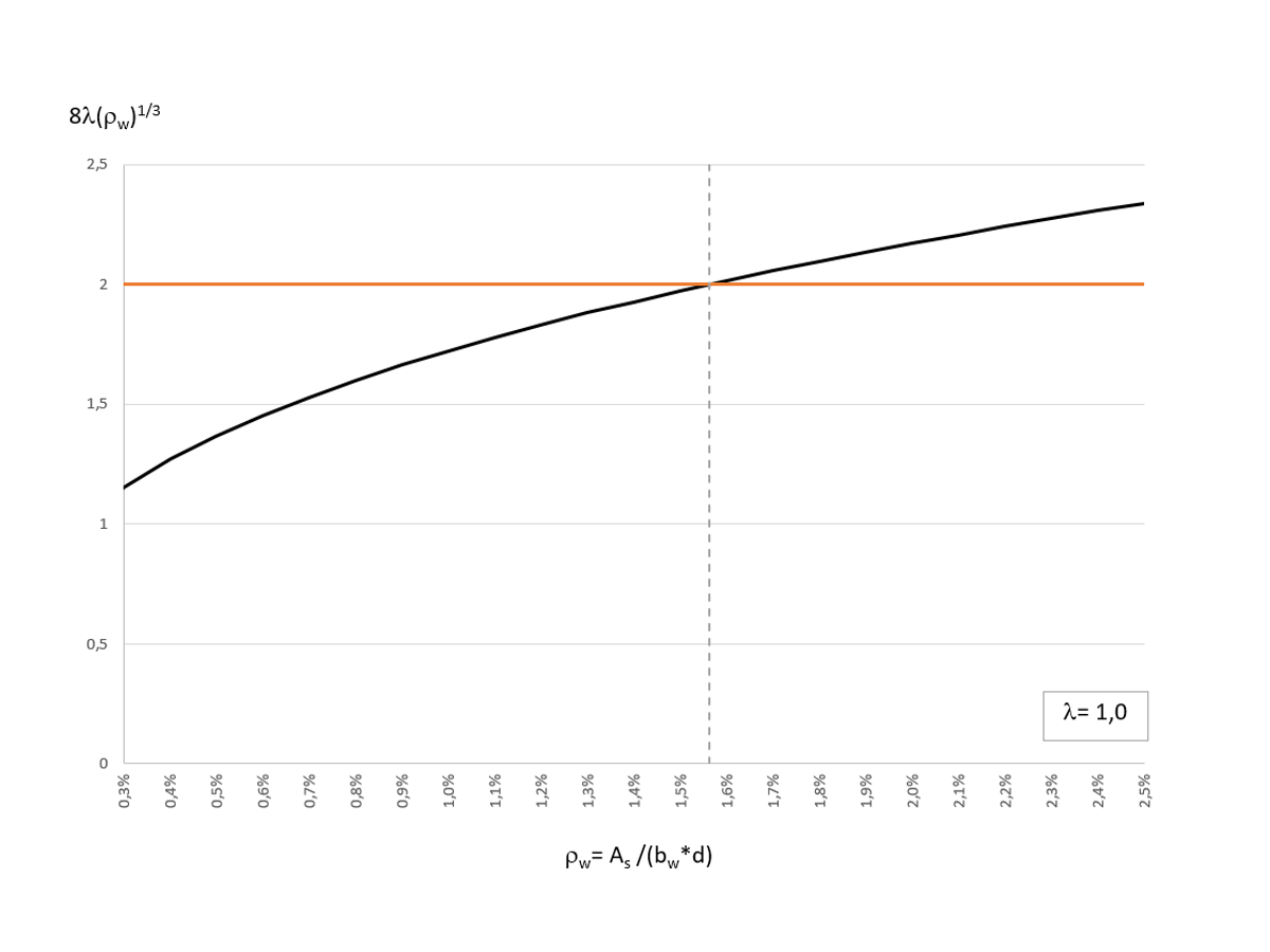
If you compare the two equations shown above, you can see that in Equation b), the factor 2 λ has been replaced by the term 8 λ (ρw)1/3. Il rapporto di armatura longitudinale ρw influenza il calcolo della resistenza a taglio Vc. Image 01 shows the distribution of 8 λ (ρw)1/3 as a function of ρw (with λ = 1).
Per λ = 1.0, 8 λ (ρw)1/3 diventa uguale al valore 2 λ per un rapporto di armatura longitudinale ρw = 1,56%. When calculating Vc, Equation a) for λ= 1 and a longitudinal reinforcement ratio ρw (greater than) 1.56% and Equation b) for λ= 1 and ρw > 1.56% results in the greater concrete shear resistance. The standard allows the application of both equations. Therefore, the maximum value from Equations a) and b) can be used for a cost-effective design.
For beams with shear reinforcement Av less than Av,min, Equation c) of Table 22.5.5.1 [1] is to be used according to ACI 318-19 [1].
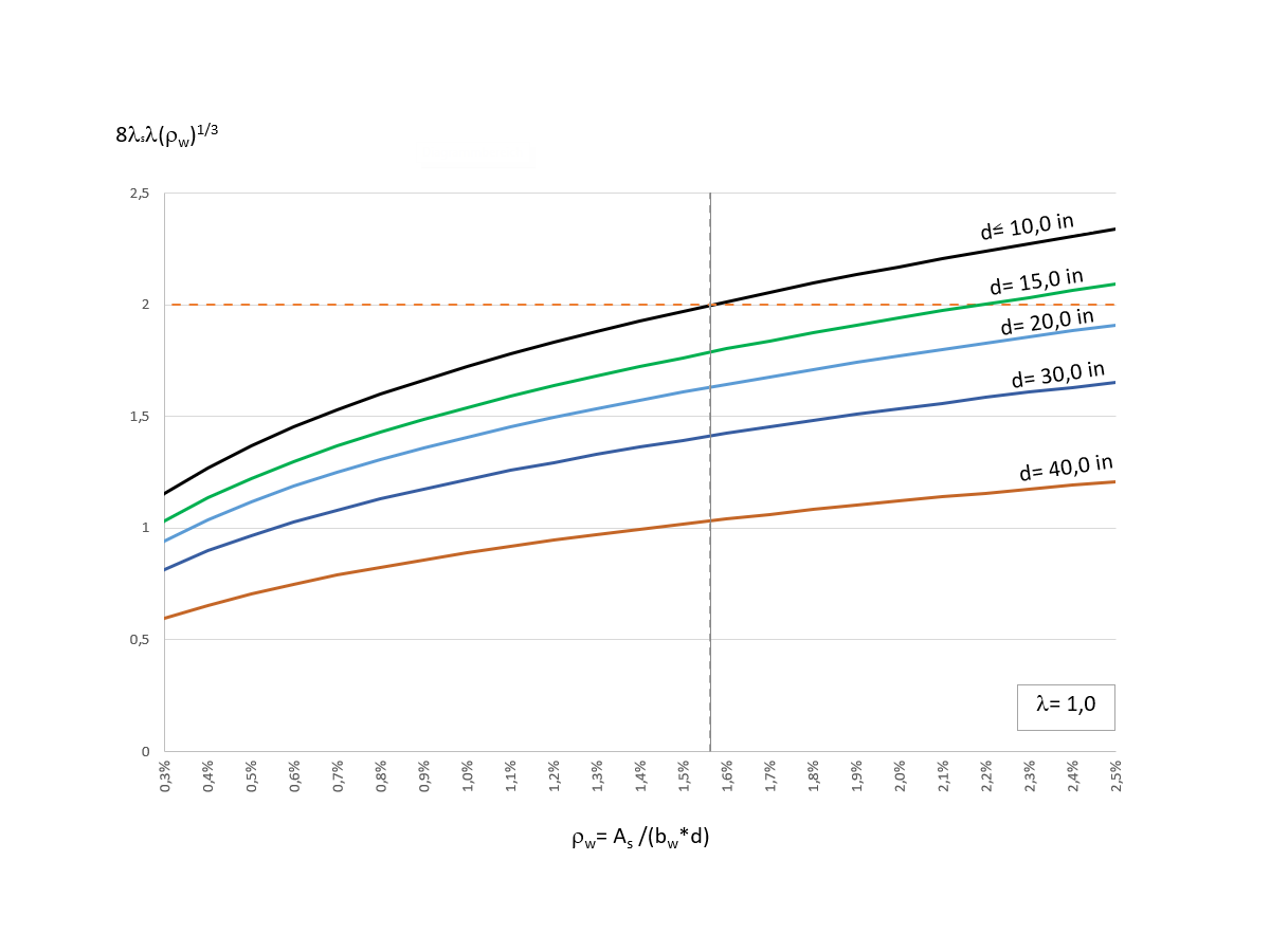
Eccetto per la variabile λs, l' equazione c) è simile all'equazione b) sopra discussa. For structural components with little or no shear reinforcement, the concrete shear resistance Vc decreases with increasing structural component height. Introducendo il coefficiente λs, viene preso in considerazione l' "Effetto dimensione". The factor λs is determined according to Equation 22.5.5.1.3 [1] as follows.
The reduction of the shear resistance Vc,c by the factor λs is only effective for structural heights d (greater than) 10in. La figura 02 mostra la distribuzione del termine 8 λs λ (ρw)1/3 per diverse altezze efficaci d.
Esempio: Calcola l'armatura a taglio necessaria secondo ACI 318-19
The following section describes how to determine the required shear reinforcement according to the new concept of ACI 318-19 [1] for a reinforced concrete beam, which was designed in a previous Knowledge Base Article according to ACI 318-14 [2]. La Figura 03 mostra il modello strutturale e il carico di progetto.
The rectangular cross-section has the dimensions 25 in. · 11 in. The concrete has a compressive strength of f'c = 5,000 psi. The yield strength of the reinforcing steel used is fy = 60,000 psi. The effective depth of the tension reinforcement is applied with d = 22.5 in. The design value of the acting shear force Vu at a distance d from the support is 61.10 kips.
The determination of the shear resistance Vs according to Table 22.5.5.1 [1] depends on the height of the inserted shear reinforcement Av. The prerequisite for using Equations a) and b) is that the minimum shear reinforcement according to 9.6.3.4 [1] is applied. For this reason, a check is performed in the first step as to whether a minimum reinforcement has to be considered according to 9.6.3.1 [1].
61.10 kips > 13.13 kips
Ciò richiede un'armatura a taglio minima. This is calculated according to 9.6.3.4 [1], as follows.
av,min = 0.12 in²/ft
When considering the minimum shear reinforcement, the concrete shear resistance Vc can now be determined with Equations a) or b) of Table 22.5.5.1 [1]. The shear resistance Vc,a according to Equation a) is calculated as Vc,a = 35.0 kips. To apply Equation b), it is necessary to know the longitudinal reinforcement ratio ρw. To be able to compare the calculated shear reinforcement with the calculation result of the Concrete Design Add-on, ρw is determined with the required longitudinal reinforcement at the distance d from the support. A bending moment of My,u = 1533 kip-in results in a longitudinal reinforcement of As,req = 1.33 in², which is ρw = 0.536%. Image 01 shows the influence of the longitudinal reinforcement ratio ρw on the calculation of Vc,b. Since ρw (less than) 1.5% here, Equation b) will result in a lower shear resistance Vc,b than Equation a) and we can skip determining Vc,b. However, we calculate Vc,b to show it.
Vc,b = 24.52 kips
Come previsto, l'equazione b) fornisce una resistenza al taglio inferiore rispetto all'equazione a).
Additionally, the shear resistance Vc is limited to the maximum value Vc,max according to 22.5.5.1.1 [1].
av,min = 0.12 in²/ft
When considering the minimum shear reinforcement, the concrete shear resistance Vc can now be determined with Equations a) or b) of Table 22.5.5.1 [1].
La resistenza a taglio Vc,a secondo l'equazione a) è calcolata come Vc,a = 35.0 kips.
Per applicare l'equazione b), è necessario conoscere il rapporto di armatura longitudinale ρw. To be able to compare the calculated shear reinforcement with the calculation result of the Concrete Design Add-on, ρw is determined with the required longitudinal reinforcement at the distance d from the support. A bending moment of My,u = 1533 kip-in results in a longitudinal reinforcement of As,req = 1.33 in², which is ρw = 0.536%. Image 01 shows the influence of the longitudinal reinforcement ratio ρw on the calculation of Vc,b. Since ρw (greater than) 1.5% here, Equation b) will result in a lower shear resistance Vc,b than Equation a) and we can skip determining Vc,b. However, we calculate Vc,b to show it.
Vc,b = 24.52 kips
Come previsto, l'equazione b) fornisce una resistenza al taglio inferiore rispetto all'equazione a).
Additionally, the shear resistance Vc is limited to the maximum value Vc,max according to 22.5.5.1.1 [1].
Vc,max = 87.5 kips
Infine, il calcolo dell'armatura a taglio necessaria risulta nella seguente resistenza alla forza di taglio del calcestruzzo applicabile Vc.
Vc = max [Vc,a; Vc,b ] ≤ Vc,max
Vc = [35.0 kips; 24.5 kips] ≤ 87.5 kips
Vc = 35.0 kips
The required shear reinforcement req. av is calculated as follows:
Req. av = 0.41 in²/ft ≥ 0.12 in2/ft
The reinforced concrete design according to ACI 318-19 [1] can be performed with RFEM 6. The Concrete Design Add-on also calculates a required shear reinforcement of 0.43 in²/ft at the distance d from the support (see Image 04).
Nota: The results in RFEM 6 differ from the hand calculations slightly due to a more accurate value for the Depth (d) calculated. RFEM 6 takes into account that there are multiple layers of tension reinforcement where the hand calculations assume a single layer.
Infine, la capacità massima di carico del puntone in compressione in calcestruzzo della travatura a taglio è verificata secondo la Sezione 22.5.1.2.
61.10 kips ≤ 175.00 kips.
La verifica a taglio secondo ACI 318-19 è soddisfatta.
Come previsto, l'equazione b) fornisce una resistenza al taglio inferiore rispetto all'equazione a).
Additionally, the shear resistance Vc is limited to the maximum value Vc,max according to 22.5.5.1.1 [1].
Sommario
ACI 318-19 [1] introduced a new concept to determine the shear resistance Vc. È stato possibile ridurre il numero di possibili equazioni di progetto dalla versione precedente a tre equazioni tenendo conto dell'influenza della tensione normale, dell'altezza del componente e del rapporto di armatura longitudinale. Ciò semplifica il calcolo della resistenza a taglio Vc.
,_Table_22.5.5.1,_ACI_318-19.png?mw=760&hash=df344c4cbc6e75e1a5d3e8fc97af7028acef3a2d)
,_Table_22.5.5.1_ACI_318-19.png?mw=760&hash=52b0cc2b9521511642861a07ad54c936a9837db3)


