.svg?mw=64&hash=343d71fbdf234f1411db2920f2dff33c0dbd6231)

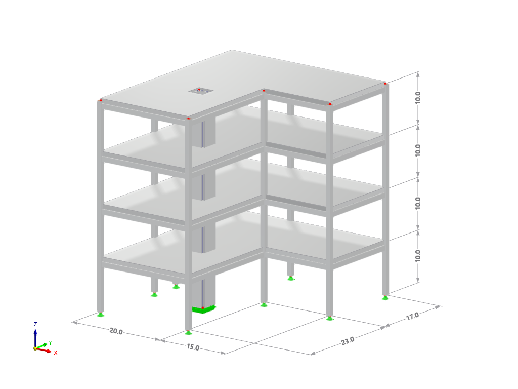
Parameterization of a Concrete Combined Footing, accepts geometry of the Footing, Columns and Soil Parameters.
- Model created by the Dlubal Latam engineering team. The model is also available as a parameterized block on the Dlubal Latam website.
The file to download contains a parametrized model saved as a block (*.rf6 file type).
Combination Footing
| Block parameters editable dynamically | |
| Number of Nodes | 12 |
| Number of Lines | 14 |
| Number of Members | 2 |
| Number of Surfaces | 6 |
| Number of Solids | 1 |
| Number of Load Cases | 3 |
| Number of Load Combinations | 2 |
| Number of Result Combinations | 0 |
| Total Weight | 17.300 tons |
| Dimensions (Metric) | 3.000 x 1.600 x 5.000 m |
| Dimensions (Imperial) | 9.84 x 5.25 x 16.4 feet |
You can download this structural model to use it for training purposes or for your projects. However, we do not assume any guarantee or liability for the accuracy or completeness of the model.


Length: 00:00:35 min

Length: 00:00:29 min

Length: 00:55:53 min

Length: 00:58:31 min
Length: 00:00:45 min
Length: 01:09:36 min
Length: 00:00:51 min

Length: 01:00:25 min


The evaluation of story drift in a building is crucial to ensure acceptable structural performance by limiting the drift amount. Excessive drift has the potential to induce system instability and may cause damage to nonstructural components such as partitions. This article outlines the procedure for establishing interstory drift according to ASCE 7-22 and the Building Model add-on in RFEM 6.
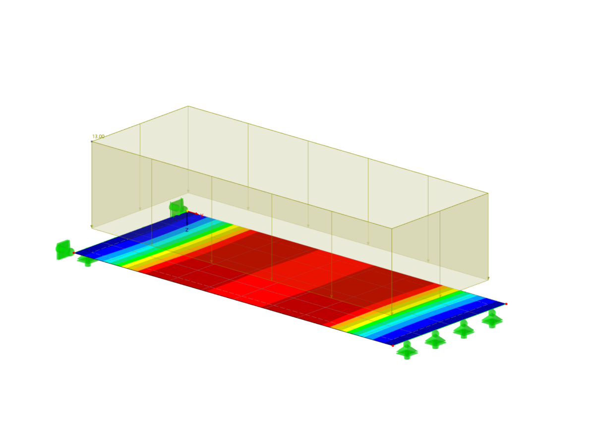
Using an example of a steel fiber-reinforced concrete slab, this article describes how the use of different integration methods and of a different number of integration points affects the calculation result.
![Spans Based on Figure 5.2 from [1]](/en/webimage/039540/3493372/01_Abmessungen_EN.png?mw=512&hash=3cc425f1463bd5981b358d5889e3109e07ae1233)
In order to correctly design a downstand beam or a T-beam in RFEM 6 using the Concrete Design add-on, it is essential to determine the flange widths for the rib members. This article describes the input options for a two-span beam and the calculation of the flange dimensions according to EN 1992-1-1.

When calculating regular structures, data input is often not complicated but time-consuming. Input automation can save valuable time. The task described in the present article is to consider the stories of a house as single construction stages. Data are entered using a C# program so that the user does not have to enter the elements of the individual floors manually.


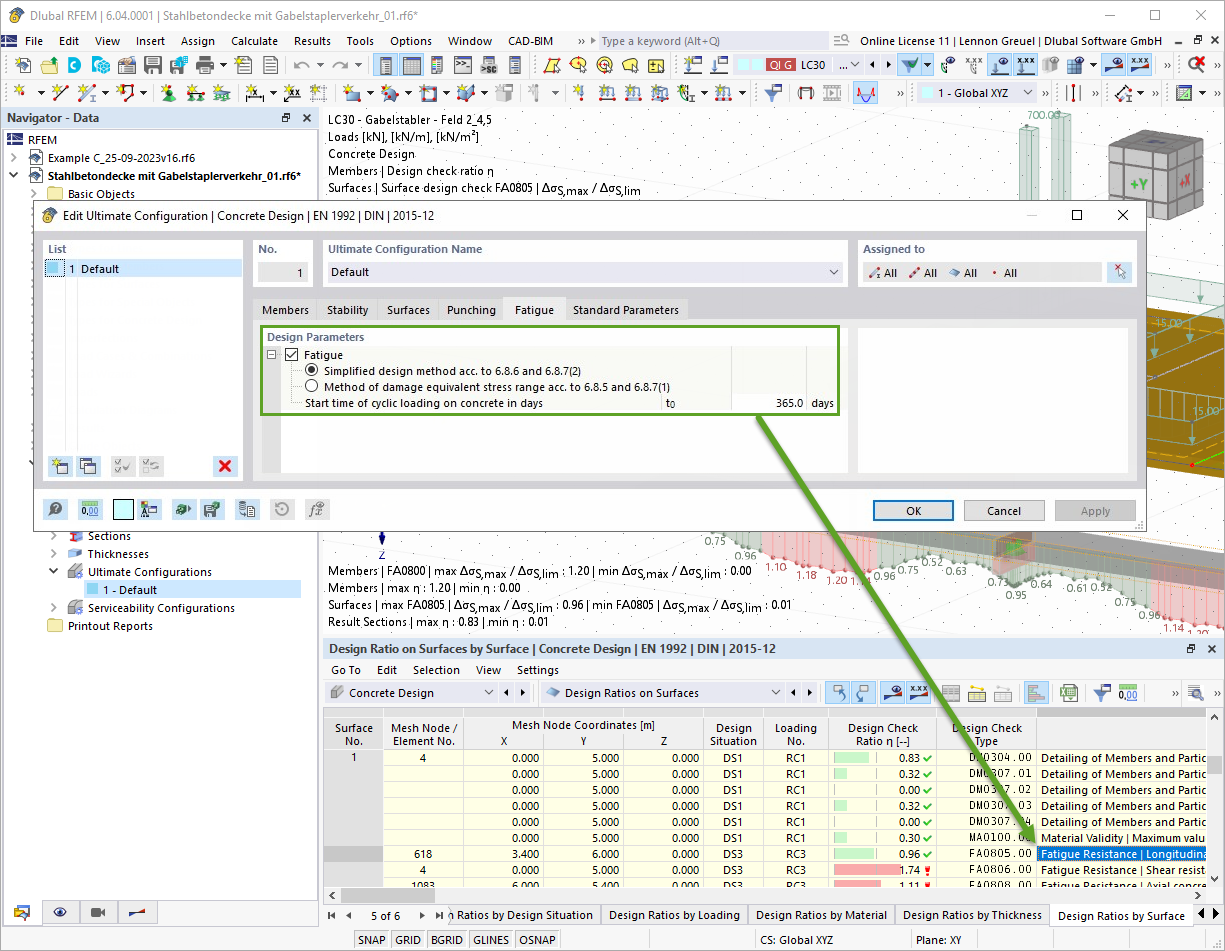
With the Concrete Design add-on, you can perform the fatigue design of members and surfaces according to EN 1992‑1‑1, Chapter 6.8.
For the fatigue design, you can optionally select two methods or design levels in the design configurations:
- Design Level 1: Simplified design according to 6.8.6 and 6.8.7(2): The simplified design is performed for frequent action combinations according to EN 1992‑1‑1, Chapter 6.8.6 (2), and EN 1990, Eq. (6.15b) with the traffic loads relevant in the serviceability state. A maximum stress range according to 6.8.6 is designed for the reinforcing steel. The concrete compressive stress is determined by means of the upper and lower allowable stress according to 6.8.7(2).
- Design Level 2: Design of damage equivalent stress acc. to 6.8.5 and 6.8.7(1) (simplified fatigue design): The design using damage equivalent stress ranges is performed for the fatigue combination according to EN 1992‑1‑1, Chapter 6.8.3, Eq. (6.69) with the specifically defined cyclic action Qfat.

The Concrete Design add-on allows you to perform the seismic design of reinforced concrete members according to EC 8. This includes, among other things, the following functionalities:
- Seismic design configurations
- Differentiation of the ductility classes DCL, DCM, DCH
- Option to transfer the behavior factor from a dynamic analysis
- Check of the limit value for the behavior factor
- Capacity design checks of "Strong column - weak beam"
- Detailing and particular rules for curvature ductility factor
- Detailing and particular rules for local ductility

In the Concrete Design add-on, you can design structural components made of fiber-reinforced concrete according to the guideline DAfStb Steel Fiber-Reinforced Concrete.
You can use this option for the design according to EN 1992‑1‑1. The design according to the DAfStb guideline is carried out once the concrete of the "Fiber Concrete" type has been assigned to the reinforced structural component.
Go to Explanatory Video
In the "Shear Reinforcement" tab, you can select the option "Cross-ties over free rebars with active selection in graphic". It allows you to arrange additional cross-ties on free rebars of the longitudinal reinforcement.
You can activate or deactivate the position of the cross-ties in the Info Graphic. The cross-ties are applied for the ultimate limit state design and the structural design checks. They are available for the design according to EN 1992‑1‑1.
Go to Explanatory Video
Why do I only obtain the total reinforcement in the Results navigator under "Required Reinforcement", and no result for the top and bottom reinforcements separately?
I would like to calculate a prestressed concrete beam. Is this possible in RFEM?
Is it possible to design a prestressed concrete slab in RFEM 6?
Is it possible to use the add-ons for RFEM 6 to design concrete solids?
Which products do you recommend for the structural analysis and design of reinforced concrete structures?
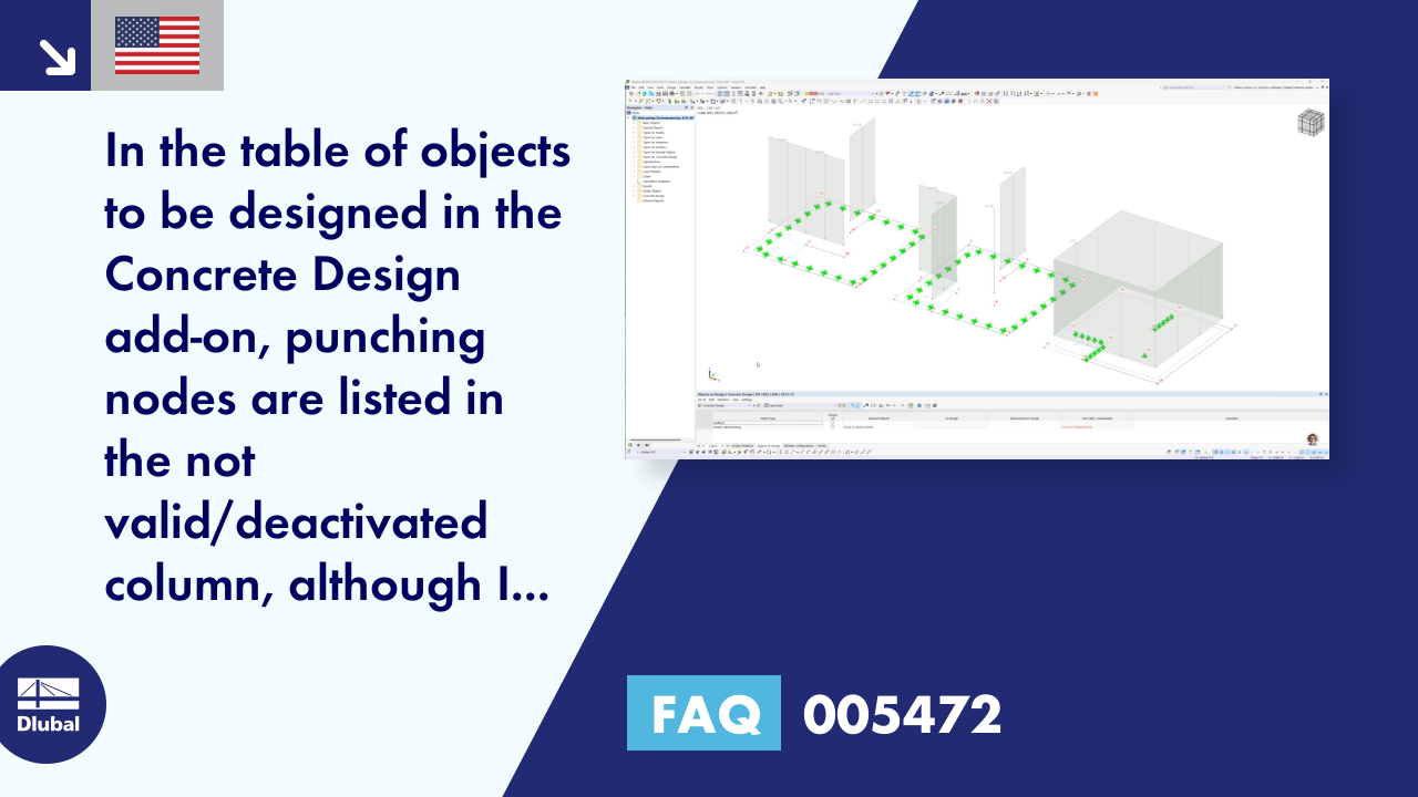
In the table of the objects to be designed in the Concrete Design add-on, punching nodes are listed in the not valid/deactivated column, although I have defined them as punching nodes. How can I fix this?


.png?mw=350&hash=87067b88e84e78e23f7a538dec586f8442297bd4)


Recommended Products for You
RFEM 6 | Main Program RFEM 6

The new generation of 3D FEA software is used for the structural analysis of members, surfaces, and solids.
Price of First License
4,170.00 USD
RFEM 6 | Design

The Concrete Design add-on allows for various design checks according to international standards. You can design members, surfaces, and columns, as well as perform punching and deformation analyses.
Price of First License
2,550.00 USD
RFEM 6 | Additional Analysis

The Construction Stages Analysis (CSA) add-on allows for considering the construction process of structures (member, surface, and solid structures) in RFEM.
Price of First License
1,570.00 USD
RFEM 6 | Additional Analysis

In RFEM, the Geotechnical Analysis add-on uses properties from soil samples to determine the soil body to be analyzed. The accurate determination of soil conditions significantly affects the quality of the structural analysis of buildings.
Price of First License
1,120.00 USD
RFEM 6 | Dynamic Analysis

The Modal Analysis add-on allows for the calculation of eigenvalues, natural frequencies, and natural periods for member, surface, and solid models.
Price of First License
1,210.00 USD
RFEM 6 | Dynamic Analysis

The Response Spectrum Analysis add-on performs seismic analysis using multi-modal response spectrum analysis. The spectra required for this can be created in compliance with the standards or can be user-defined. The equivalent static forces are generated from them. The add-on includes an extensive library of accelerograms from seismic zones that can be used to generate the response spectra.
Price of First License
1,390.00 USD
RFEM 6 | Dynamic Analysis

Using the Pushover Analysis add-on, you can analyze the seismic actions on a particular building, and thus assess whether the building can withstand an earthquake.
Price of First License
1,300.00 USD
RFEM 6 | Special Solutions

The Building Model add-on for RFEM allows you to define and manipulate a building using stories. The stories can be adjusted in many ways afterwards. The information about stories and the entire model (center of gravity) is displayed in tables and graphics.
Price of First License
1,660.00 USD
RFEM 6 | Design

The Masonry Design add-on for RFEM allows you to design masonry using the finite element method. It was developed as part of the research project titled DDMaS – Digitizing the Design of Masonry Structures. The material model represents the nonlinear behavior of the brick-mortar combination in the form of macro-modeling.
Price of First License
1,660.00 USD