


Thema:
Beurteilung der Geschossverschiebung unter Erdbebenlasten gem. ASCE 7-22 und Gebäudemodell
Kommentar:
Die Beurteilung der Geschossverschiebung in einem Gebäude ist entscheidend, um eine akzeptable Tragleistung durch Begrenzung der Verschiebungsmenge sicherzustellen. Eine übermäßige Verschiebung kann zu einer Systeminstabilität führen und kann zu Schäden an nichttragenden Bauteilen wie Trennwänden führen. In diesem Beitrag wird das Verfahren zur Ermittlung der Stockwerksverschiebung gemäß ASCE 7-22 und dem Add-On Gebäudemodell in RFEM 6 erläutert.
Beschreibung:
'''Ermittlung der Nullpunktverschiebung nach ASCE 7-22'''
Gemäß ASCE 7 wird die Bemessungsgeschossverschiebung Δ als Differenz der Bemessungserdbebenverschiebungen δ-DE nach Abschnitt 12.8.6.3 berechnet. Die Ebenenverformung δ-di kann bei der Ermittlung der Bemessungsgeschossverschiebung nach Abschnitt 12.8.6.5 vernachlässigt werden.
|
δx |
Gesamtverschiebung eines Stockwerks [in (mm)] |
|
Cd |
Vergrößerungsfaktor der Auslenkung nach Tabelle 12.2-1 |
|
δxe |
Auslenkung an der geforderten Stelle, durch eine elastische Analyse ermittelt [in (mm)] |
|
Ie |
Bedeutungsbeiwert, definiert in Abschnitt 11.5.1 |
'''Lastkombination für Verschiebungsberechnung'''
Gemäß Abschnitt 12.8.6.1 muss die elastische Analyse zur Berechnung der Verschiebung auf 1.0Eh in Kombination mit den zu erwartenden Gewichtslasten basieren. Die Gewichtslast wird einbezogen, um Übereinstimmung zwischen den Kräften, die in der Verschiebungsanalyse verwendet werden, und den Kräften, die für den Stabilitätsnachweis verwendet werden (P – Δ) [ASCE 7 Kommentar C12.8.6]. Die Lastkombination 1.0Eh + 1.0D + 0.5L ist für Nutzlasten anwendbar, die kleiner gleich 100 psf sind (Ausnahme 1, Abschnitt 2.3.1).
'''Ort der Verschiebungsauswertung (ASCE 7 Abschnitt 12.8.6.5)'''
1) Wenn die Massenschwerpunkte (CoM) ausgerichtet sind, wird die Geschossverschiebung basierend auf den Verschiebungen des Massenmittelpunkts berechnet.
2) Wenn die CoM nicht ausgerichtet sind (Exzentrizität zwischen den CoM zweier benachbarter Geschosse beträgt mehr als 5% der Breite der Scheibe), basiert die Verschiebung, die am unteren Geschoss berechnet wird, auf der vertikalen Projektion der CoM des oberen Geschosses (Kommentar zu C12.8.6).
3) Für Bauwerke, die der Erdbebenbemessungskategorie C, D, E oder F zugeordnet sind und torsionssteif sind, wird die Verschiebung entlang der '''Ränder''' des Bauwerks mit zwei vertikal ausgerichteten Punkten berechnet.
'''Add-Ons Modalanalyse & Antwortspektrenverfahren'''
Um die Thematik zu erläutern, wird ein dreigeschossiges Betongebäude mit einem L-förmigen Grundriss als Beispiel verwendet (Bild 01). Zunächst wird die Modalanalyse durchgeführt, um die Eigenfrequenzen und Eigenformen der Struktur zu erhalten.

Danach wird mittels Antwortspektrumverfahren (RSA) das Antwortspektrum nach der Norm ASCE 7-22 generiert. Die verschiebungsbezogenen Parameter Cd und Ie können bereits bei der Erstellung des Antwortspektrums mit einbezogen und somit in der Berechnung der Geschossverschiebungen berücksichtigt werden. In diesem Beispiel wird Cd = 1,5 und Ie = 1,0 verwendet (Bild 02).

Mit dem Add-On Gebäudemodell werden die Massenzentrumslagen nach Berechnung für die Spektralanalyse für jedes Geschoss bereitgestellt. In der Tabelle 'Mittelpunkt von Masse und Steifigkeit' ist zu erkennen, dass die CoM zwischen den angrenzenden Decken nicht ausgerichtet sind (Bild 03).
Für die Auswertung der Geschossverschiebung muss zuerst der CoM für jedes Geschoss als Knoten angelegt werden. Der Knoten 47 wird im obersten Stockwerk bei Z = 12,3 m hinzugefügt. Da die am unteren Geschoss berechnete Verschiebung auf der vertikalen Projektion des CoM des oberen Geschosses basiert, wird eine Kopie des Knotens bei Z = 9,2 m hinzugefügt, wodurch der Knoten 73 erzeugt wird. Dieses Vorgehen kann im Anschluss für die unteren Geschosse fortgeführt werden.

Bei der Berechnung der Geschossverschiebung ergibt sich eine kritische Überlegung: Die Differenz der Verschiebungen darf nicht aus den bereits quadratisch überlagerten Ergebnissen ermittelt werden, sondern darf erst nach Ermittlung der Differenz überlagert werden. Daher gilt folgende Formel:
Aufgrund dieser Bedingung können die Verschiebungen der Umhüllenden aus "X" nicht direkt für die Auswertung genutzt werden. Stattdessen muss die Geschossverschiebung für jede Eigenform in jede Richtung einzeln beurteilt und dann manuell überlagert werden.
Lässt man sich die Verschiebung ux in den Massenschwerpunkten eines jeden Geschosses anzeigen, kann die Geschossverschiebung aus den Differenzen zwischen übereinander liegenden Punkten abgeleitet werden (Bild 04).
Eigenformen mit minimaler Massenbeteiligung (z. B. in diesem Fall Eigenform 5 und 7) können über das Register "Wahl der Formen" unter dem RSA-Lastfall von der Berechnung ausgeschlossen werden.

In der unteren Tabelle sind die relevanten Eigenformen und deren Verschiebungen aufgelistet (Bild 05).
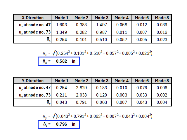
Dieses Vorgehen muss für jedes Geschoss durchgeführt werden. Dadurch lässt sich die maximale Geschossverschiebung für das gesamte Gebäude ermitteln. Der Ansatz der Gravitationslasten wird zur Vereinfachung nicht dargestellt.
'''Verwehungsberechnung nach dem Add-On Gebäudemodell'''
Für die Ermittlung der Stockwerksverschiebung kann das Add-On Gebäudemodell hilfreich sein. Die Methodik zur Berechnung der Verschiebung folgt jedoch nicht dem oben beschriebenen ASCE 7-Ansatz.
Die Lage der Stockwerksverschiebung, die in der Tabelle 'Stockwerksverschiebung' (Bild 6) angegeben ist, basiert im Gebäudemodell nicht unbedingt auf einem bestimmten Punkt (d...