.svg?mw=64&hash=343d71fbdf234f1411db2920f2dff33c0dbd6231)

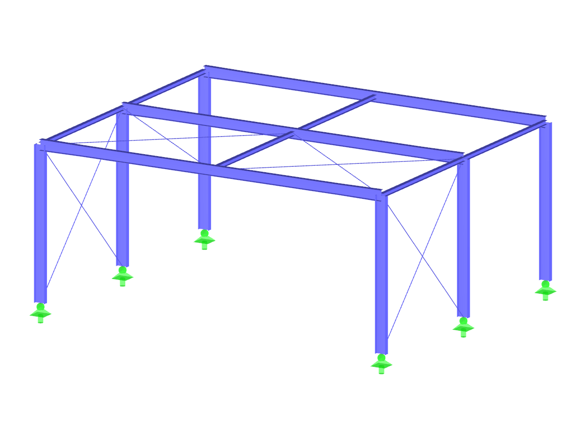
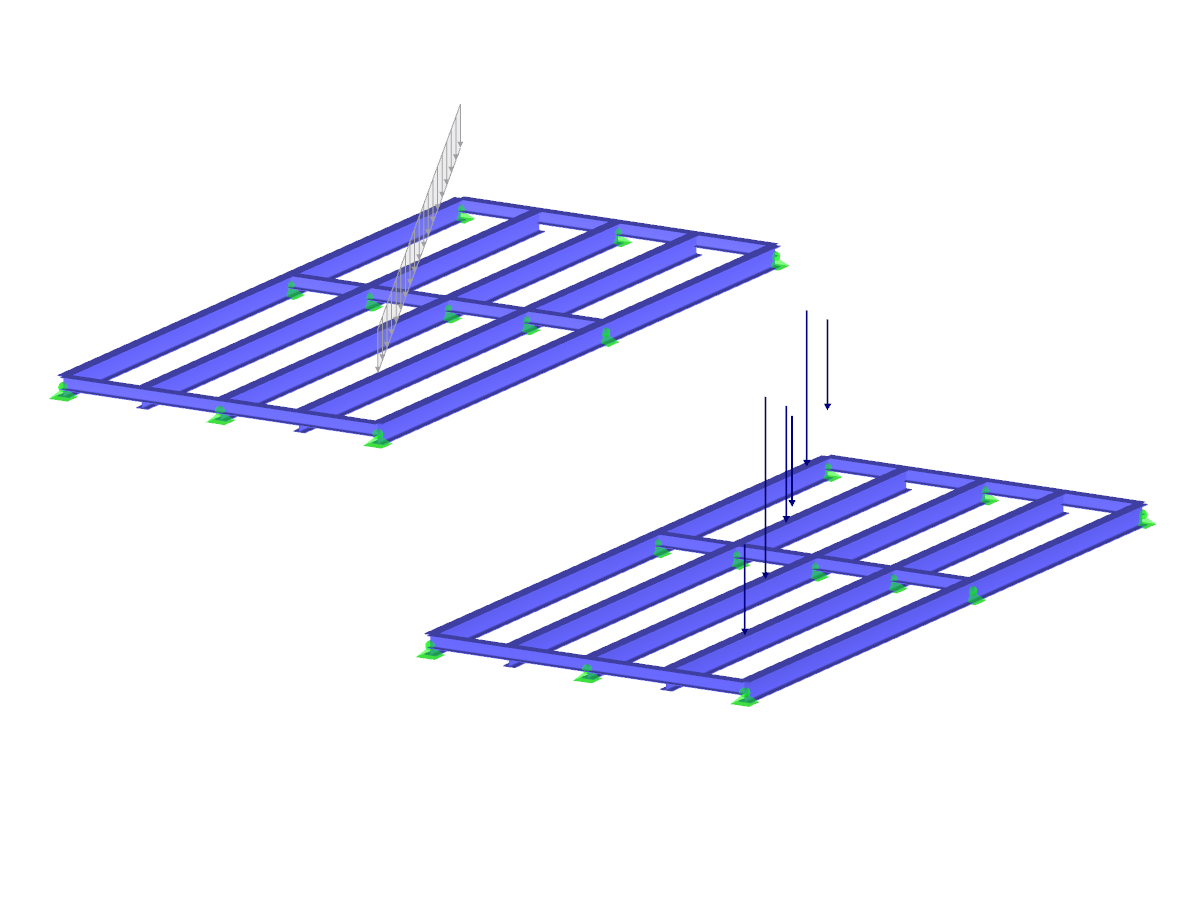
Steel Building
No Download Possible
Customer Project / View Only
| Number of Nodes | 44 |
| Number of Members | 59 |
| Number of Load Cases | 7 |
| Number of Load Combinations | 76 |
| Number of Result Combinations | 4 |
| Total Weight | 8.044 tons |
| Dimensions (Metric) | 16.500 x 5.500 x 8.444 m |
| Dimensions (Imperial) | 54.13 x 18.04 x 27.7 feet |
| Program Version | 8.01.00 |
Related Models