Not extended scissor lift
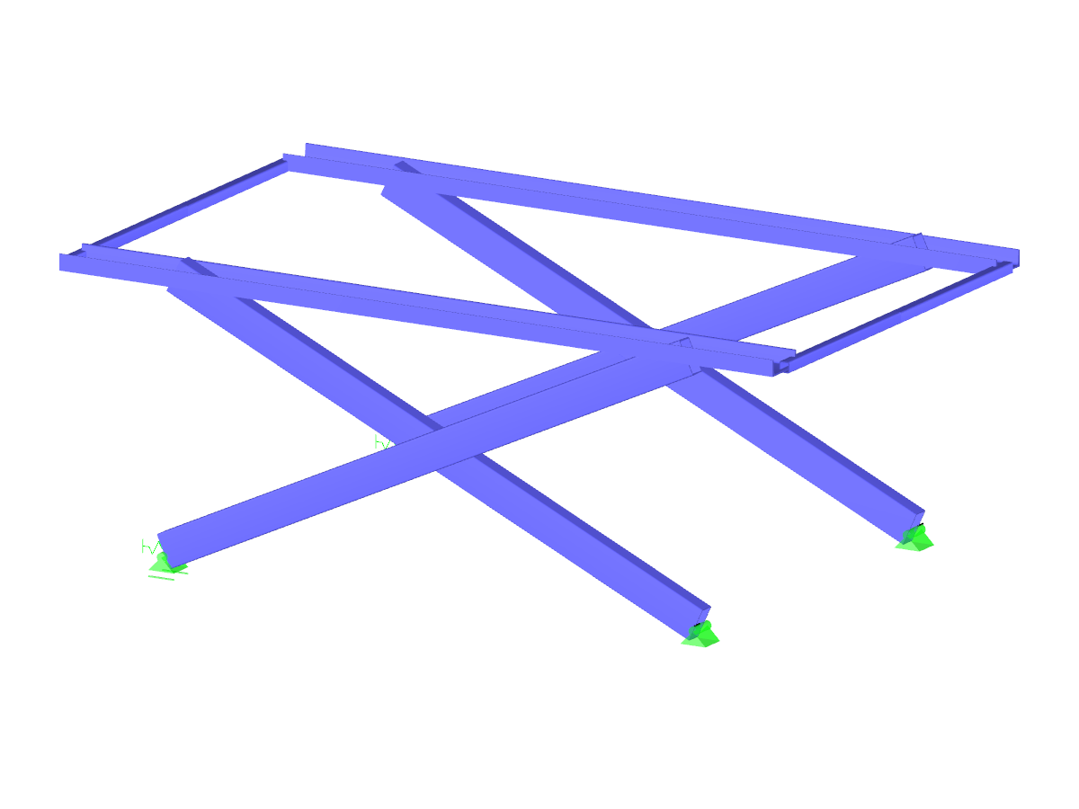
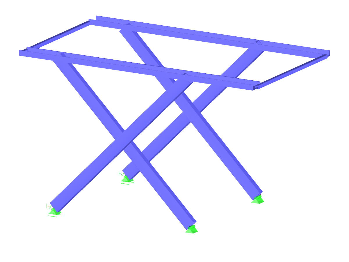
Scissor Lift | Not Extended
Number of Nodes | 26 |
Number of Lines | 28 |
Number of Members | 28 |
Number of Surfaces | 0 |
Number of Solids | 0 |
Number of Load Cases | 1 |
Number of Load Combinations | 0 |
Number of Result Combinations | 0 |
Total Weight | 0.404 tons |
Dimensions (Metric) | 3.500 x 0.394 x 1.980 m |
Dimensions (Imperial) | 11.48 x 1.29 x 6.5 feet |
You can download this structural model to use it for training purposes or for your projects. However, we do not assume any guarantee or liability for the accuracy or completeness of the model.
Related Models
![Scissor Lift](/en/webimage/013457/2847437/main.png?mw=512&hash=e35b0ba070a5f9f25a45fda767a74f3ef4ab5d05)
It is necessary to design some structures in different configurations. It may be that an aerial work platform must be analyzed in its position on the ground as well as in the middle and in the extended position. Since such tasks require the creation of several models, which are almost identical, updating all the models with just one mouse click is a considerable relief.
![Scaffolding Release Dependent on Normal Force](/en/webimage/010058/2422416/01-en-png-2-png.png?mw=512&hash=a176425574684ded7575c2c4b3e4e0ddd024384d)
In RFEM, you can simulate a scaffolding tube joint (butt joint with a stub) by a nonlinear member release of the "Scaffolding" type. The joint considers moment resistance dependent on compression forces existing between two outer tubes, and the stub also has certain moment resistance based on its bending resistance.
![Scaffolding Support](/en/webimage/010185/3073549/01-en_Scaffolding_Support.png?mw=512&hash=9e646894d583fc6cc433d6df162b5e20c4fdcc69)
Temporary structures, such as scaffolding or props, are versatile structures that can be adapted very well to different geometric conditions.
![KB 001874 | LTB Analysis According to ADM 2020 Section F.4 in RFEM 6](/en/webimage/048099/3772420/2024-03-18_15-43-26.png?mw=512&hash=418d15db74dbdf280bc2956def625d5b0eb8704f)
Lateral-Torsional Buckling (LTB) is a phenomenon that occurs when a beam or structural member is subjected to bending and the compression flange is not sufficiently supported laterally. This leads to a combination of lateral displacement and twisting. It is a critical consideration in the design of structural elements, especially in slender beams and girders.
![Feature 002842 | Sign-Dependent Stress Analysis](/en/webimage/051240/3953337/1.png?mw=512&hash=9d7f6c198b6d4ae6ee8f2fa8bca75f85579e14c9)
In the Stress-Strain Analysis add-on, you can use the option to specify sign-dependent limit stresses by stress component.
![Feature 002827 | Stresses Within Members](/en/webimage/050679/3922742/50679.png?mw=512&hash=89c2586ec7139690a213073aaa5a3e314c7ed023)
Get a better understanding of the stress distribution within member cross-sections by using clipping planes.
![Feature 002426 | Animation of Deformation](/en/webimage/032091/3328083/AnimationRFEM6_EN.jpg?mw=512&hash=ecf9e52031e929ead1b99a37bfa7e0b1c3a2f4f2)
The deformation process of the global deformation components can be represented as a movement sequence.
![Feature 002423 | Displaying Results in Solids](/en/webimage/031923/3325382/FE_Solid_EN.jpg?mw=512&hash=d2950a5e2123942fab13aad296e814c67695c955)
The results of solid stresses can be displayed as colored 3D points in the finite elements.
Recommended Products for You