.svg?mw=64&hash=343d71fbdf234f1411db2920f2dff33c0dbd6231)

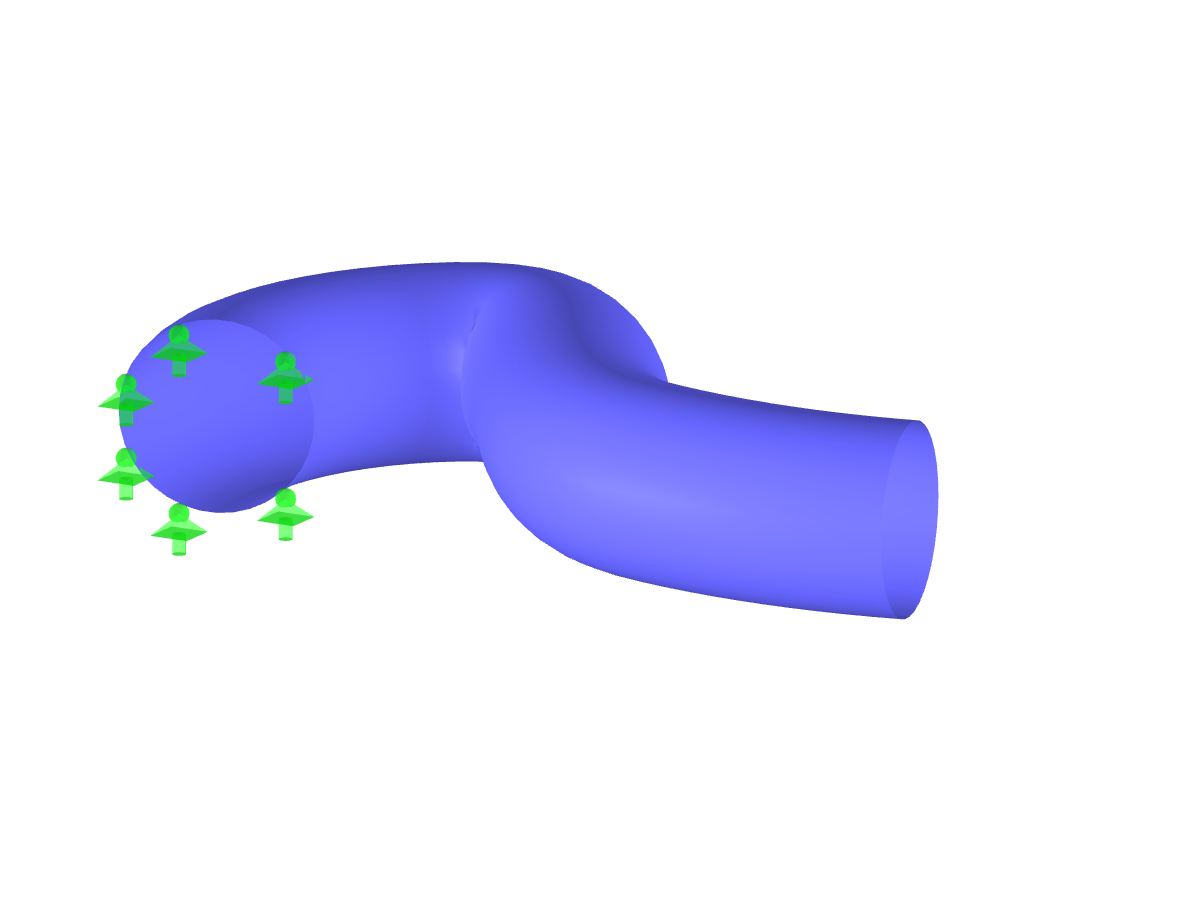
Pipe
No Download Possible
Customer Project / View Only
| Number of Nodes | 95 |
| Number of Lines | 33 |
| Number of Surfaces | 10 |
| Number of Solids | 1 |
| Number of Load Cases | 1 |
| Total Weight | 1.721 tons |
| Dimensions (Metric) | 2.505 x 1.505 x 1.731 m |
| Dimensions (Imperial) | 8.22 x 4.94 x 5.68 feet |
| Program Version | 4.08.08 |
Related Models