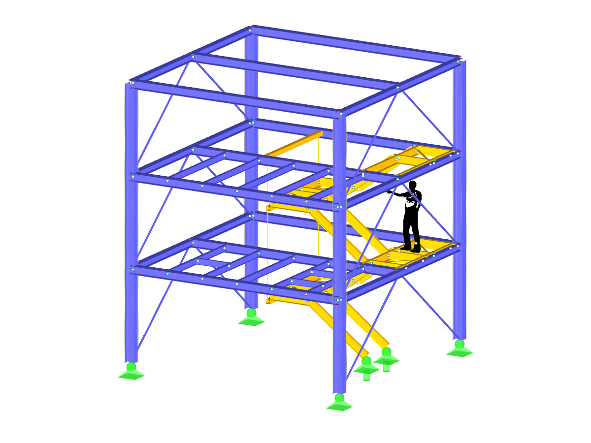
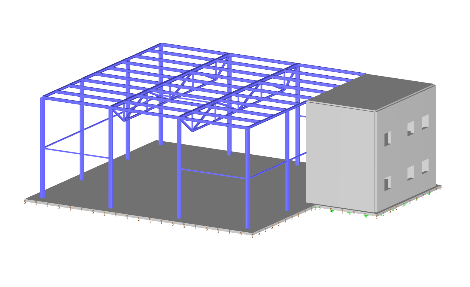
Model for Webinar "Design of Cold-Formed Steel Sections According to Eurocode 3"
Model Used in
- RFEM 6 | Structural Dynamics and Seismic Design According to EC 8
- RFEM 6 | Dynamic Analysis and Seismic Design According to EC 8
- RFEM 6 | Basics
- RFEM 6 | Structural Dynamics and Seismic Design According to EC 8
- RFEM 6 | Dynamic Analysis and Seismic Design According to EC 8
- RSECTION | Students | Introduction to Strength of Materials
- RFEM | Basics | HTW Saar
- RFEM 6 | Basics
- RFEM 6 | Basics
- RFEM 6 | Structural Dynamics and Seismic Design According to EC 8
- RFEM 6 | Dynamic Analysis and Seismic Design According to EC 8
- RFEM 6 | Basics | Deggendorf Institute of Technology
- RSECTION | Students | Introduction to Strength of Materials
- RFEM 6 | Dynamic Analysis and Seismic Design According to EC 8
- RSECTION | For Students | Introduction to Strength of Materials
- RFEM 6 | Dynamic Analysis and Seismic Design According to EC 8
- RSECTION | Students | Introduction to Strength of Materials
- Tips and Tricks Using Navigator and Printout Report in RFEM
- Eurocode 3 | Steel Design - Theory and Practical Examples According to DIN EN 1993-1-1
- RFEM | Basics
- RFEM | Basics
- RFEM | Basics
- RFEM | Structural Dynamics and Seismic Design
- RFEM | Structural Dynamics and Seismic Design According to EC 8
- RFEM | Basics
- RFEM | Dynamic analysis and anti-seismic design according to EC 8
- RFEM | Structural dynamics and earthquake design according to EC 8
- RFEM | Structural Dynamics and Seismic Design According to EC 8
- RFEM | Structural dynamics and earthquake design according to EC 8
- RFEM | Structural Dynamics and Seismic Design According to EC 8
- RFEM | Basics
- RFEM | Basics
- Eurocode 8 | Structural Dynamics and Seismic Design
- RFEM | Dynamics | USA
- RFEM | Structural Dynamics and Seismic Analysis According to EC 8
- Online Introductory Training RFEM - KTH Royal Institute of Technology
- RFEM | Dynamic Analysis and Seismic Design According to EC 8
- RFEM | Structural Dynamics and Seismic Analysis According to EC 8
- RFEM 5 | Basics
- RFEM | Structural Dynamics and Seismic Design According to EC 8
- RFEM 5 | Structural Dynamics and Seismic Design According to EC 8
- RFEM 6 | Basics
- RFEM 6 | Structural Dynamics and Seismic Design According to EC 8
- RFEM 6 | Dynamic Analysis and Seismic Design According to EC 8
- RFEM 6 | Basics
- RFEM 6 | Basics
- RFEM 6 for Students | Introduction to Strength of Materials | Apr 26, 2023
- RFEM 6 for Students | Introduction to Strength of Materials
Model for Webinar Design of Cold-Formed Steel Sections According to Eurocode 3
Number of Nodes | 121 |
Number of Members | 225 |
Number of Load Cases | 9 |
Number of Load Combinations | 38 |
Number of Result Combinations | 2 |
Total Weight | 16.369 tons |
Dimensions (Metric) | 20.500 x 25.500 x 5.598 m |
Dimensions (Imperial) | 67.26 x 83.66 x 18.37 feet |
Program Version | 8.23.01 |
You can download this structural model to use it for training purposes or for your projects. However, we do not assume any guarantee or liability for the accuracy or completeness of the model.
Related Models
3250x
167x
5318x
133x
![Model](/en/webimage/011774/2600584/01-de.png?mw=512&hash=9f2525444a7414dfb1c05a73e375e9c4fe4f47b1)
Designing rigid end plate connections is difficult for four-row connection geometries and multi-axis bending stresses, because there are no official design methods.
![System with Local Axis System of Gusset Plate](/en/webimage/011743/3065040/01_-_en_us.jpg?mw=512&hash=2a77856259cebbe0dd4f7bd67111e0e92e909dd2)
The European standard EN 1993-1-8, Section 4.5.3.3. provides the user with a simplified method for the ultimate limit state design of fillet welds. According to the standard, the design is fulfilled if the design value of the resultant acting on the fillet weld area is smaller than the design value of the weld's load-bearing capacity. Thus, if you want to dimension the weld for a surface model, you will be faced with a variety of results due to the nature of FEM calculations. Therefore, we show in the following text how to determine the force components from the model.
![KB 001883 | Plate Girder Design According to AISC 360-22 in RFEM 6](/en/webimage/051561/3980997/im1.png?mw=512&hash=b8237709c4f30213fac51d86d32a42bddde72f03)
Plate girder is an economical choice for long spans construction. I-section steel plate girder typically has a deep web to maximize its shear capacity and flange separation, yet thin web to minimize the self-weight. Due to its large height-to-thickness (h/tw) ratio, transverse stiffeners may be required to stiffen the slender web.
![Steel Connection Rigidity and Its Influence on Structural Design](/en/webimage/051432/3972404/Rigidity-caseA.png?mw=512&hash=3be64e68ab2956fd2b92f0afa1559b3a8c72b468)
Understanding steel connection rigidity is crucial in structural design. Often, connections are treated as strictly pinned or rigid, but this can lead to uneconomical or even dangerous designs. Explore how Dlubal Software's RFEM and Steel Joints add-on help verify connection stiffness and moment resistance, ensuring safer and more economical designs.
![Add-on "Steel Joints for RFEM 6" | Component Library](/en/webimage/043097/3898884/steel_joints_components.png?mw=512&hash=e4f835906155863fc7019d5043b22e553dc766f9)
- Numerous component types, such as base and end plates, web angles, fin plates, gusset plates, stiffeners, tapers, or ribs for easy input of typical connection situations
- Universally applicable basic components (such as plates, welds, bolts, auxiliary planes) for modeling complex connection situations
- Graphical display of the connection geometry with dynamic updating during the input
- Wide range of cross-section shapes: I-sections, U-sections, angles, T-sections, hollow sections, built-up cross-sections and thin-walled sections
- Library in the Dlubal Center with a large number of program-side template connections, including user-defined templates
- Automatic adaptation of the connection geometry based on the relative arrangement of the components to each other – even in case of subsequent editing of the structural components
![Feature 002820 | Limit Plastic Strain for Welds](/en/webimage/050344/3881226/1.png?mw=512&hash=9d7f6c198b6d4ae6ee8f2fa8bca75f85579e14c9)
In the ultimate configuration of the steel joint design, you have the option to modify the limit plastic strain for welds.
![Component "Base Plate"](/en/webimage/050345/3936120/50345.png?mw=512&hash=3bd641cb1a2445804b338855e4debfc40c6563e9)
The "Base Plate" component allows you to design base plate connections with cast-in anchors. In this case, plates, welds, anchorages, and steel-concrete interaction are analyzed.
![Feature 002807 | 3D Display of FSM Results](/en/webimage/049281/3861162/2024-05-01_10-32-55.png?mw=512&hash=2377d291bc20ac3d78d617b50c131614e99ac6f7)
In the "Edit Section" dialog box, you can display the buckling shapes of the Finite Strip Method (FSM) as a 3D graphic.
Recommended Products for You