In reality, the singularities or the resulting stress concentrations do not occur to the extent as they appear in the model. Basically, a result evaluation in singularity locations is not reasonable. However, examining and questioning singularity is very reasonable, as the singularity locations can indicate problems in the real model. A practical example in concrete design would be the analysis of a punching risk in the area of singularity locations.
In the case of concrete design in RFEM and RF-CONCRETE, singularities often cause failed design.
Where can singularities occur?
- Point-like supports or load introduction
- Reentrant corners or corners of openings
- Stiffness jumps (jump in plate thickness, for example)
- Start and end of ribs
- Start and end of line supports or walls
Detecting Singularities
Singularity locations can be identified in the FEA by refining the mesh at the corresponding location in the model using the FE mesh refinement. If the stress-dependent result value in the considered area increases but the respective area decreases, it is very likely a singularity location.
Preventing Singularities
Singularities and the accompanying design failure can be prevented in various ways in RFEM and the reinforced concrete design with RF-CONCRETE.
Average Region
In RFEM, average regions are available that can be used to smooth the maximum result values or set to zero. An average region can be created by clicking the corresponding option under “Results” in the menu bar. When averaging, the basic region must be determined. For example, by using the option “Set internal forces to zero”, the cross-section of a connected column can be used as the range (see Image 01).
Integrated Surface
As an alternative to the average region with dimensions of the column cross-section, it is possible to model surfaces and integrate them into the existing surfaces. These surfaces are then excluded from the design in RF-CONCRETE Surfaces (see Image 01).
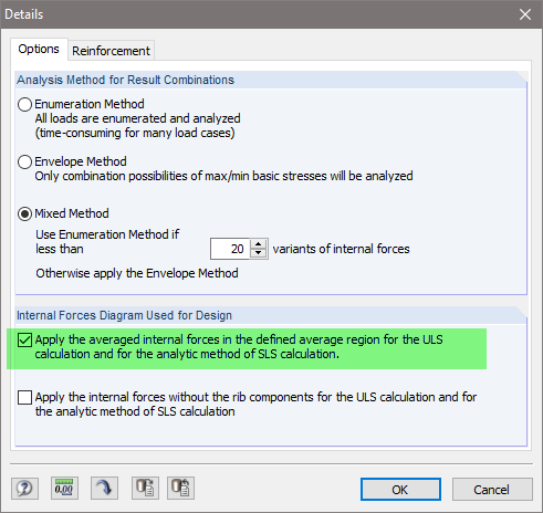
The option of using the averaged internal forces or the internal forces set to zero must be activated in Details of RF-CONCRETE Surfaces (see Image 02).
Both methods (average region and integrated surface) can be used for both columns and reentrant corners. In general, average regions are sufficient. However, the average regions do not have the desired effect for a nonlinear calculation, as the internal forces can be rearranged during the calculation and new singularity effects may arise.
Design Method for Walls
When designing walls, singularities can occur due to the high axial forces, for example, due to singular supports. In addition, the design method can have a significant impact on the singularity effects or design failure. Therefore, it is recommended to deactivate the optimization of design internal forces in RF-CONCRETE Surfaces in the case of walls (see Image 03).
Distributed Load Introduction
To avoid the singularity effects, concentrated or line loads can be converted to surface loads. This option can be found in the shortcut menu, for example (see Image 04).
Rounding Reentrant Corners
In the case of reentrant corners and corners at openings, it is possible to round the corner using the “Create Round or Angled Corner” function, if necessary. This function can be selected in the menu bar under “Tools”. However, many singularity effects can be sufficiently prevented by using averaged regions.
Support
Preventing singularities on nodal and line supports is explained in this technical article:


