Существует несколько методов модификации объектов, используемых в соединении. Один из них — компонент Сечение стержня. С помощью него можно изменить конец элемента в области соединения в целом. Существует четыре вида резки, основанные на референтном объекте для резки: резка по стержню, по пластине, по вспомогательной плоскости и по вспомогательному объему.

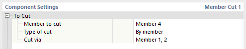
Для резки
В первой категории области Настройки компонента можно выбрать элемент для резки, а затем установить тип резки. Как упомянуто выше, существуют типы «по стержню», «по пластине», «по вспомогательной плоскости» и «по вспомогательному объему». Поскольку Настройки резки зависят от выбранного типа резки, детальное описание каждого типа резки предоставляется ниже. В любом случае, в последней строке указывается референтный объект, который является определяющим для резки.
Настройки резки
Детали ввода в этой категории зависят от выбранного типа резки.
По стержню
Тип резки по стержню используется, когда стержень (Резка с помощью) определяет пространство другого стержня (Стержень для резки), чтобы обеспечить геометрию без столкновений.
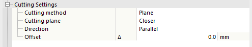
Первая строка в категории Настройки резки управляет методом резки. Первый из доступных методов — это опция «Плоскость, которая резает по плоскости ограничивающего каркаса референтного элемента. Второй метод — опция Площадь. Она обрезает только пересечение поперечных сечений.
_Plane_(left),_Surface_(right).png?mw=760&hash=27e152b827b62742cdc5fcff5a4378659ef3f3a2)
Опции Ограничивающий каркас и Выпуклая оболочка особенно подходят для создания резок асимметричных сечений.
Метод резки символизируется битмапами в графической области диалогового окна, которые вы можете активировать с помощью кнопки
![]() .
.
При резке по плоскости можно выбрать, какая площадь резки является определяющей, т.е., находится ли она «ближе или дальше к прилегающему стержню. Стандартное состояние — ближе, так как это более частый случай. Ниже приведены некоторые примеры для обоих опций резки. На первом изображении показаны элементы без резки. На среднем изображении балка режется над опорой, установка опции «Плоскость» на «Ближе». На последнем изображении добавлено новое сечение стержня, где опора режется над балкой, установка опции «Плоскость» на «Дальше».
,_Closer_(middle),_Farther_(right).png?mw=760&hash=f2437a33cede294697038a70877b74ec624317ac)
Последняя настройка, которая относится специально к резке по плоскости, — это направление резки. Существует два варианта: Параллельно или Перпендикулярно. Параллельно означает, что плоскость резки параллельна референтному элементу (Резка с помощью). Направление Перпендикулярно означает, что плоскость резки перпендикулярна оси прилегающего стержня в точке контакта обоих стержней.

Для всех методов резки возможно также указать смещение, при котором происходит фактическая резка. Для Плоскости и Площади допустимы как положительные, так и отрицательные значения.
По вспомогательной плоскости
Вместо существующего элемента можно использовать вспомогательную плоскость в качестве референтного объекта. В этом случае дополнительные настройки состоят из направления резки и смещения, аналогично резке по стержню. Опции для направления такие же: Параллельно вспомогательной плоскости или Перпендикулярно оси прилегающего стержня в ближайшей точке контакта со вспомогательной плоскостью.
_Parallel_(left),_Perpendicular_(right).png?mw=760&hash=8f8bf2e8d1dfe914557ff1d39cbda38c9a4643b2)
По пластине
Тип резки По пластине подобен резке по вспомогательной плоскости. Основное различие в том, что вспомогательная плоскость не имеет толщины, тогда как пластина имеет. Поэтому метод резки может быть выбран как Плоскость или Площадь. Помимо метода резки, существуют дополнительные настройки Направление и Смещение, как описано выше.
__Parallel_(left),_Perpendicular_(right).png?mw=760&hash=9d7f268cb7b9d2a4872c1b4cf3f1876e0595720b)
По вспомогательному объему
Тип резки По вспомогательному объему позволяет трёхмерную резку стержня без определённого референтного элемента. Пересечение стержня, подлежащего резке, с вспомогательным объемом удаляется в соответствии с заданным смещением.
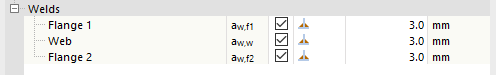
Сварные швы
В случаях, когда в результате резки возникает контакт между пластинами или пластинами стержней, может быть определён сварной шов. Для каждого контакта кромки пластины и поверхности пластины появляется новая строка определения сварного шва в категории Сварные швы в области Настройки компонента. Определение содержит флажок, чтобы указать, использовать ли сварной шов, поле Тип сварного шва и для Филейный шов опция для определения толщины сварного шва.