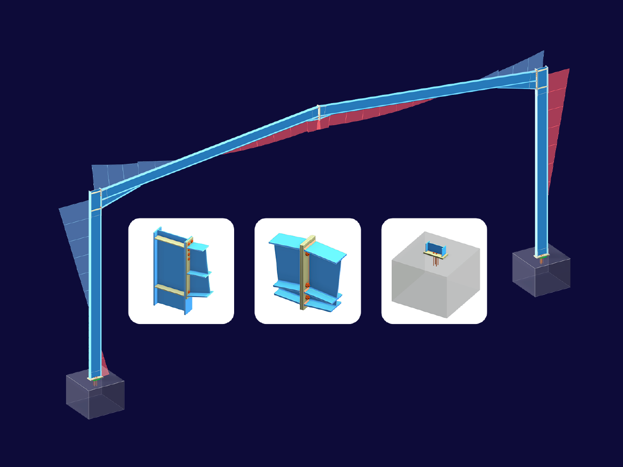
L'add-on Giunti acciaio, disponibile come estensione per RFEM 6, consente la creazione di innumerevoli collegamenti derivanti dalla pratica della verifica acciaio. It uses the component-based finite element method (CBFEM) and seamlessly links the design of the connections with the static calculation of the overall structure.
Among the numerous new features in the add-on with which we at Dlubal strive to make modeling and designing steel connections as simple and fast as possible for you, two are particularly important for this text: the ability to model circular hollow sections and the ability to model stiffened connections for members of this profile type using the "rib" component. In this regard, the purpose of this article is to show you the advantages of having the "rib" component at your disposal for modeling stiffened tubular connections such as the one shown in Image 1. To do this, the connection shown in the image is first modeled without using the component, then modeled by simply inserting the component and adjusting its settings.
Modeling Ring Flange
Let's look at the components we need before we take a look at both of the methods for modeling ribs. Since we are going to connect two member elements, a bolted end plate connection can be used (Image 2). To model this in the Steel Joints add-on, you will need the following components: Plate-to-Plate, Plate Editor, and Fasteners. Please note that the connection consists of two plates that need to be changed in shape from rectangular to round, so you will need to insert and properly adjust the Plate Editor twice (once for each plate).
If you want to see the settings of each component in detail, you can do so by downloading the model provided at the end of the article. The article titled KB 1887 on our website also provides a deeper insight into how to insert these components and adjust their settings.
Modeling Ribs
Having inserted the above components and properly defined their settings, let's look at rib modeling in the program before and after providing the rib component as a single component for direct insertion from the component library.
Modeling Without Using “Rib” Component
In older versions of the program, rib modeling was done as described in this section. First, you had to insert a Plate to have the rib on one side of the ring. Then you had to insert two Plate Cuts for it: one for the cut across the end plate and one for the cut across the connecting member. Note that the first cut type is "plate" while the second is "by member". To get the right shape of the plate, a Plate Editor would have had to be added to adjust the rib corners by chamfering them. This way, you would have had to insert 4 separate components and define their settings to model one rib alone (Image 3).
Next, you would need to insert the same 4 components again to add another rib to the joint. Even if you copied the components, you would still need to make adjustments, such as the position of the plate, so that the rib sits in the right place. Given that there are 8 ribs on one side of the ring plate (one at each 45-degree angle), you would have needed 6 more ribs on this side alone, which would have resulted in using the same 4 components 8 times (that is, 32 components overall) and properly adjusting the position of each plate to end up with a rib at each 45-degree angle.
But that's not all; the entire process would have to be repeated for the other side of the ring plate, so that ultimately 64 components would be needed to create the connection shown in Image 1.
Modeling Using “Rib” Component
Since the method described above for modeling ribs is quite time-consuming, our development team at Dlubal has made this process much easier and more straightforward for you by providing the "Rib" component for use on circular sections, as in this example. Hence, all you have to do now is insert the component using the "Insert component at start/end" function and make the settings as shown in Image 5. You learned about these settings in the article KB 1890.
In addition, you can now define all the ribs on one side of the ring plate at the same time by adjusting their number in the settings, as shown in Image 5. This means that to have the ribs on the other side of the ring plate (in relation to Member 2), you only need to copy this component once and then simply change the stiffened object to “Member 2 | Wall” and the reference object from “Plate to Plate 1 | Plate 1” to “Plate to Plate 1 | Plate 2” as shown in Image 6.
This way, you only need to insert 2 components to stiffen the ring flange and make the connection, as in Image 1. This is a big difference from the 64 components you once had to insert to model the rib alone.
Conclusioni
Our mission at Dlubal is to constantly provide you with tools that make your work in our programs easy, fast, and straightforward. In this context, the component library in the Steel Joints add-on has been extended with the "Rib" component, which is now also available for use on members with circular hollow sections. This way, modeling stiffened tubular joints like the one shown in this article is very simple and efficient: in addition to the components needed to model the ring flange, you only need to insert two "Rib" components and let the ring flange be stiffened by these components. The stiffening, in turn, is important to avoid problems such as the prying effect on the connecting elements, which will be covered in an upcoming Knowledge Base article.


..png?mw=320&hash=bd2e7071b02d74aef6228d22c4b83867d2d7e1a5)


.png?mw=350&hash=d48786243b6e6ea52c46161d98f18495d06c047f)


_1.jpg?mw=350&hash=ab2086621f4e50c8c8fb8f3c211a22bc246e0552)


