To divide a line or member, right-click the object. In the shortcut menu, select one of the functions for Divide Line or Divide Member.

You can also divide lines or members using the
![]() and
and
![]() or
or
![]() and
and
![]() buttons in the CAD toolbar (see image
Modeling Tools
).
buttons in the CAD toolbar (see image
Modeling Tools
).
Divide Using Intermediate Nodes
Use this function to divide the line or member into equal segments.

Number
Enter the 'Number of intermediate nodes' n for the division. For example, a member is divided by two intermediate nodes at its one-third points, as shown in the image above.
Options
The 'Create On Member nodes without dividing member' check box is deactivated by default. When dividing the member or line, new members and lines are created. If you select the check box, the member or line remains as a whole. In this case, the division is carried out using intermediate nodes of the 'Node on Member' or 'Node on Line' type (see Nodes chapter). Then, there is no need to define continuous members, and entering effective lengths and boundary conditions for the design is made easier.

If you select the 'Individual numbering' check box, you can influence the numbering of the new objects in the Numbering tab.
Numbering
The Numbering tab is displayed if the Individual numbering check box is selected in the 'Main' tab.
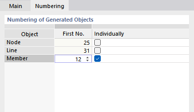
In the 'Individually' table column, select the object to which you want to assign a specific numbering. Then, in the 'First No.' column, you can specify the start number for the new objects. Further objects of this category are numbered in ascending order from this number.
Divide Using Distance
Use this function to divide the line or member at a particular location.

Distance Between New Node and Line/Member start or Line/Member end
Specify the distance from the start or end node where the line or member is to be divided. You can enter the value as a length or relative specification. The four input fields are interactive.
If the distance refers to a projected length, specify the projection in the 'Reference Length' dialog section.
Reference Length
Define the 'Coordinate system' in which the division is to be carried out. You can select a user-defined coordinate system in the list or use the
![]() button.
button.
In most cases, the division distance refers to the 'True length' of the line or member. If this is not the case, select the relevant 'Projection in direction' of an axis of the specified coordinate system or the corresponding 'Projection in plane'. Then, you can enter the corresponding division entries in the 'Distance' dialog section.
Options
The 'Create On Member nodes without dividing member' check box controls whether new objects are generated when dividing the member or line (see the Options paragraph).
If you select the 'Individual numbering' check box, you can influence the numbering of new generated objects (see the Numbering tab).
Please note that you make the division with the
![]() button. If you then use the
button. If you then use the
![]() button, the selected objects are divided again. If you do not want this to happen, close the dialog with
button, the selected objects are divided again. If you do not want this to happen, close the dialog with
![]() .
.