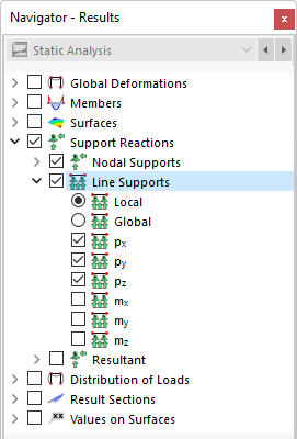
You can display the results for supported lines graphically, using the Support Reactions category. If there are line releases, you can control the deformations and forces in the Releases category. You can find the numerical results of the line supports and line releases in the Results by Line table category.
.png?mw=760&hash=be729bb2b92f8a8e54b99aedcec474505a11a50f)
Support Forces
The Results by Line in Table image shows the table with the support forces of the lines. Support forces are designated as "p", support moments as "m". They are usually related to the local axis system of lines. In the navigator, you can specify which components are displayed graphically.
The table lists the support forces and moments by line. The "Location x" describes the distance of the FE node from the line start.
The table shows the forces and moments that are introduced into the line support. Thus, with regard to signs, the table does not show the reaction forces or moments on the part of the support. The signs result from the direction of the global axes. If the global Z-axis is directed downwards, the "self-weight" load case, for example, results in a positive global support force pZ. Thus, the support forces shown in the table represent the foundation loads.
The local support forces are related to the local axis system of the lines; the signs of the introduced forces thus result from the directions of the local support axes. You can display and hide them using the shortcut menu of line supports.
In contrast to the results in the table, the "Support Reactions" vectors in the graphic represent the reaction forces and moments on the part of the supports. The components are visualized by the size and direction of the vectors. A positive support moment acts clockwise about the respective positive axis.
Sum of Loads and Sum of Support Forces
For load cases and load combinations, the check sums Σ of loading and support forces are indicated at the end of the table. This balance will show a difference if the model also has nodal supports, member supports, or surface supports. Those support forces must also be considered in the overall balance.
Result Diagrams of Support Forces
You can also display the support forces graphically in the 'Result Diagram' window: Select the line support. Then, use the Result Diagrams for Selected Line Supports function in the Results menu. You can also right-click the line support and select Result Diagrams in the shortcut menu.
.png?mw=760&hash=9a9aadb70b0cd9d19d3e284d8f46725e0008d768)
The "Result Diagrams" window is described in the Result Diagrams chapter.
Line Release Deformations


As described in the Line Releases chapter, copies of the original lines are created with a line release. The displacements and rotations of these generated copies are shown in the graphic and in the table.
The local displacements and rotations correspond to the "Release Type Conditions" of the line release types. They have the following meaning:
| ux | Displacement in the direction of the local x-axis |
| uy | Displacement in the direction of the local y-axis |
| uz | Displacement in the direction of the local z-axis |
| φx | Rotation about the local x-axis |
Line Release Forces

You can control the graphical results by selecting Forces in the "Releases" category (see the image Results for Line Releases). The "Line Release Forces" table shows the internal forces of the released lines that are present in each FE mesh point. The values are length-related and correspond to the "Release Type Conditions" of the line release types:
| n | Longitudinal force in the direction of the local axis x |
| vy | Shear force in the direction of the local y-axis |
| vz | Shear force in the direction of the local z-axis |
| mx | Moment about the local x-axis |
FAQ 004954 explains how to interpret the signs of the line release forces.
The table also shows the average values and the resultants PX, PY, and PZ for each line (see the image Line Release Forces in Table). The resulting forces are each related to the global coordinate system. You can display the resultants graphically using the Resultants navigator category.

In the technical article Direction and Reference of Section and Release Resultant, you can find more information about evaluating the resultants.