
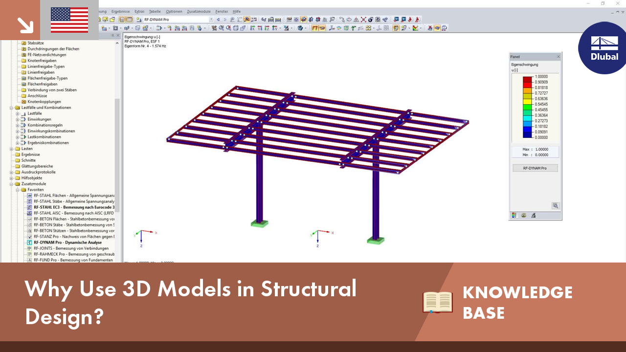
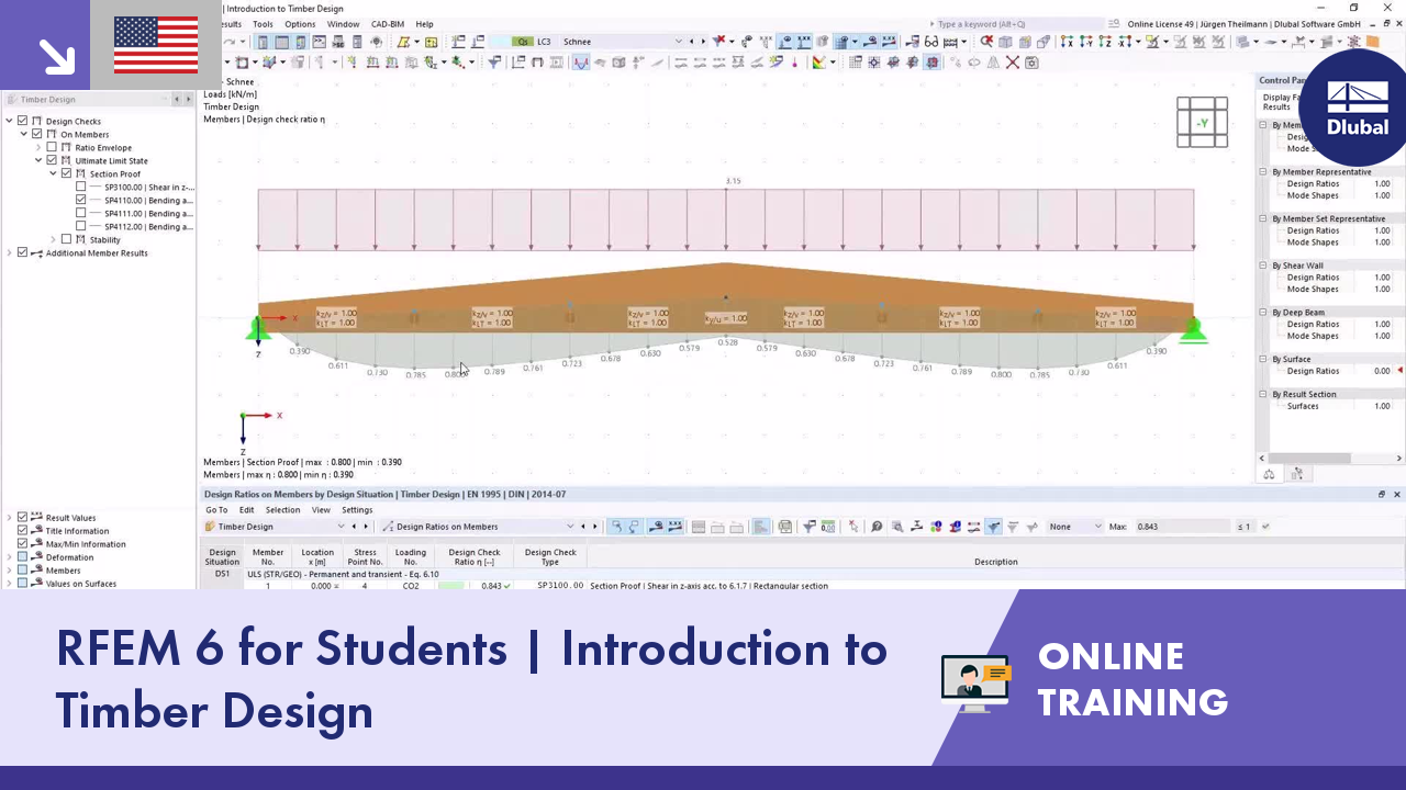
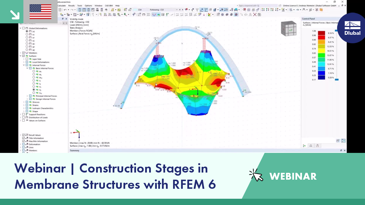
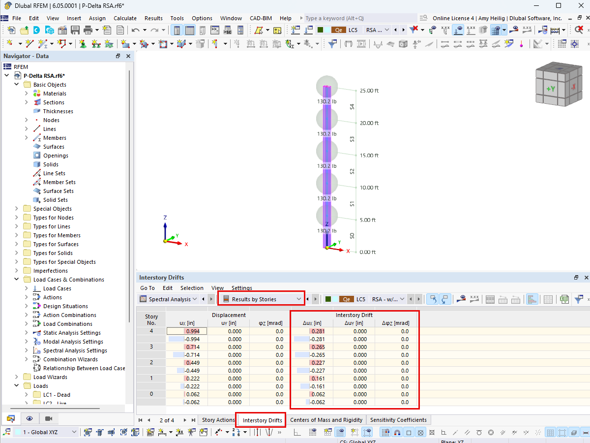
Structures are naturally three-dimensional. However, because it was impossible to perform calculations on three-dimensional models easily in the past, the structures were simplified and broken down into planar subsystems. With the increasing performance of computers and related software, it is often possible to do without these simplifications.


.png?mw=600&hash=49b6a289915d28aa461360f7308b092631b1446e)


