Question
How can I display the results of the RF‑/DYNAM Pro add-on module in the printout report?
Answer:
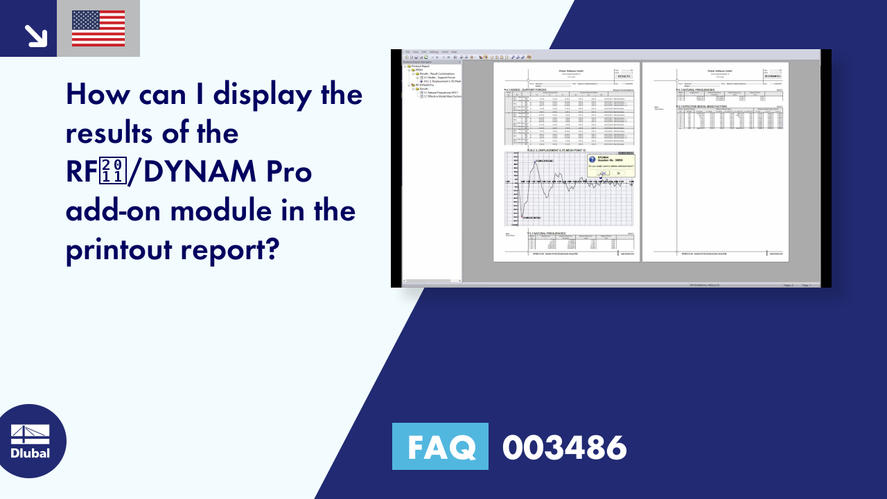
The results of the RF‑/DYNAM Pro add-on modules Forced Vibrations, Nonlinear Time History, and Equivalent Loads are not listed directly in the printout report. This is generally due to the fact that dynamic calculations require a lot of data and results.In each of the mentioned add-on modules, it is possible to create a result combination with the envelope results. In this generated result combination, you can find the same results as in the main programs and display them in the printout report as usual.
Furthermore, you can print pictures in the printout report, as usual. There is also an option to display the time history graphically in the printout report.
Do you have any questions?
In this article, you will learn how to model and design cable structures in RFEM 6 or RSTAB 9.
This article describes and explains the influence of bending stiffness of cables on their internal forces. Furthermore, the text provides information on how this influence can be reduced.
The ASCE 7-22 Standard [1], Sect. 12.9.1.6 specifies when P-delta effects should be considered when running a modal response spectrum analysis for seismic design. In the NBC 2020 [2], Sent. 4.1.8.3.8.c gives only a short requirement that sway effects due to the interaction of gravity loads with the deformed structure should be considered. Therefore, there may be situations where second-order effects, also known as P-delta, must be considered when carrying out a seismic analysis.
This article presents the basic concepts in structural dynamics and their role in the seismic design of structures. Great emphasis is given to explaining the technical aspects in an understandable way, so that readers without deep technical knowledge can gain an insight into the subject.
In RFEM and RSTAB, you can visualize the flow field quantities of pressure, velocity, turbulence kinetic energy, and turbulence dissipation rate for the wind simulation.
The clipping planes are aligned with the respective wind direction.
In the ultimate configuration of the steel joint design, you have the option to modify the limit plastic strain for welds.
Using the "Base Plate" component, you can design base plate connections with cast-in anchors. In addition to plates and welds, the design analyzes the anchorage and the steel-concrete interaction.
In RFEM, you can generate surfaces from members with the library cross-sections as well as from the members with the RSECTION cross-section.
Recommended Products for You