Question
I would like to define a line support with ineffective tension and apply the tension force on this line using a nodal support instead. Why does the line support still receive a tension force?
Answer:
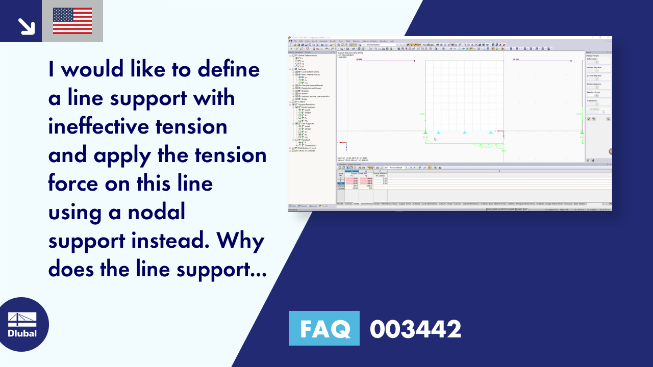
If nodal supports are modeled on supported lines, this may lead to problems and incorrect definitions. Therefore, the following warning message appears in the plausibility check.
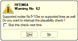
Internally, the line supports and nodal supports are treated on each FE node. If a nodal support is located on a line support, an FE node thus receives several support definitions. If the defined directions of the supports are not equal, this is not critical and the warning message can be ignored. If the same directions are defined several times, discrepancies may occur.
If the line support and the nodal support on this line fail under tension, a tensile force thus arises in the FE node, which, however, is part of the line and nodal support.
To avoid this behavior, it is possible to insert a short line without a support definition in the area of each nodal support. It may also be useful to model a tension bracket using a newly defined member. The force transmission can then be adjusted using the support of the member, the member type itself, and the member end release.
In general, the support stiffnesses should be estimated in a realistic way; in the example, rigid supports were assumed as a simplification.
Downloads
Do you have any questions?
In this article, you will learn how to model and design cable structures in RFEM 6 or RSTAB 9.
This article describes and explains the influence of bending stiffness of cables on their internal forces. Furthermore, the text provides information on how this influence can be reduced.
The ASCE 7-22 Standard [1], Sect. 12.9.1.6 specifies when P-delta effects should be considered when running a modal response spectrum analysis for seismic design. In the NBC 2020 [2], Sent. 4.1.8.3.8.c gives only a short requirement that sway effects due to the interaction of gravity loads with the deformed structure should be considered. Therefore, there may be situations where second-order effects, also known as P-delta, must be considered when carrying out a seismic analysis.
This article presents the basic concepts in structural dynamics and their role in the seismic design of structures. Great emphasis is given to explaining the technical aspects in an understandable way, so that readers without deep technical knowledge can gain an insight into the subject.
In RFEM and RSTAB, you can visualize the flow field quantities of pressure, velocity, turbulence kinetic energy, and turbulence dissipation rate for the wind simulation.
The clipping planes are aligned with the respective wind direction.
In the ultimate configuration of the steel joint design, you have the option to modify the limit plastic strain for welds.
Using the "Base Plate" component, you can design base plate connections with cast-in anchors. In addition to plates and welds, the design analyzes the anchorage and the steel-concrete interaction.
In RFEM, you can generate surfaces from members with the library cross-sections as well as from the members with the RSECTION cross-section.
Recommended Products for You