.svg?mw=64&hash=343d71fbdf234f1411db2920f2dff33c0dbd6231)

Cross-Laminated Timber Building (CLT)
| Number of Nodes | 533 |
| Number of Lines | 460 |
| Number of Members | 314 |
| Number of Surfaces | 28 |
| Number of Load Cases | 6 |
| Number of Result Combinations | 164 |
| Total Weight | 62.136 tons |
| Dimensions (Metric) | 15.600 x 10.200 x 5.935 m |
| Dimensions (Imperial) | 51.18 x 33.46 x 19.47 feet |
| Program Version | 5.23.02 |
You can download this structural model to use it for training purposes or for your projects. However, we do not assume any guarantee or liability for the accuracy or completeness of the model.


When generating shear walls and deep beams, you can assign not only surfaces and cells, but also members.

In RFEM, the oriented strand board (OSB) material is available for the USA and Canada. The material parameters are taken from the "Panel Design Specification manual".
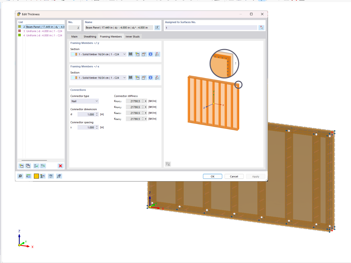
Using the "Beam Panel" thickness type, you can model timber panel elements in 3D space. You just specify the surface geometry and the timber panel elements are generated using an internal member-surface construct, including the simulation of the connection flexibility.
The building model is calculated in two phases:
- Global 3D calculation of the global model, where the slabs are modeled as a rigid plane (diaphragm) or as a bending plate
- Local 2D calculation of the individual floors
After the calculation, the results of the columns and walls from the 3D calculation and the results of the slabs from the 2D calculation are combined in a single model. This means that there is no need to switch between the 3D model and the individual 2D models of the slabs. The user only works with one model, saves valuable time, and avoids possible errors in the manual data exchange between the 3D model and the individual 2D ceiling models.
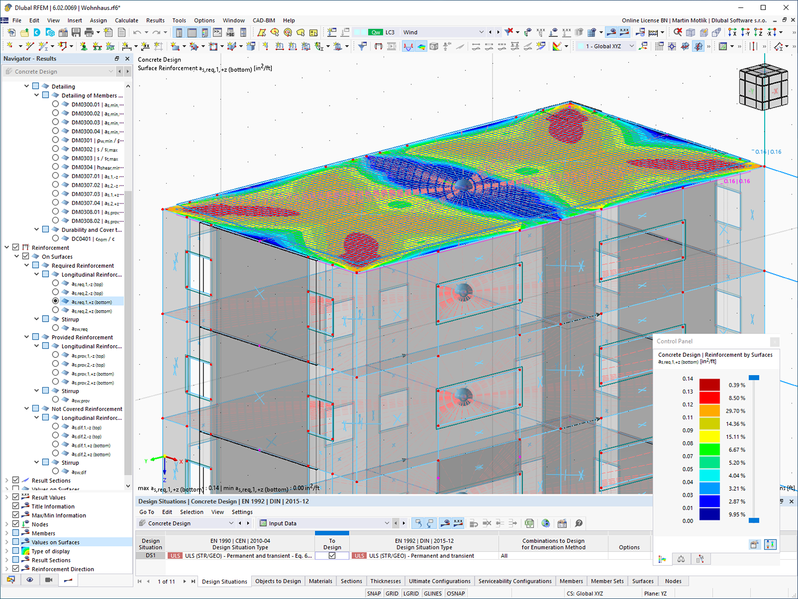
The vertical surfaces in the model can be divided into shear walls and opening lintels. The program automatically generates internal result members from these wall objects, so they can be designed as members according to any standard in the Concrete Design add-on.


The new generation of 3D FEA software is used for the structural analysis of members, surfaces, and solids.

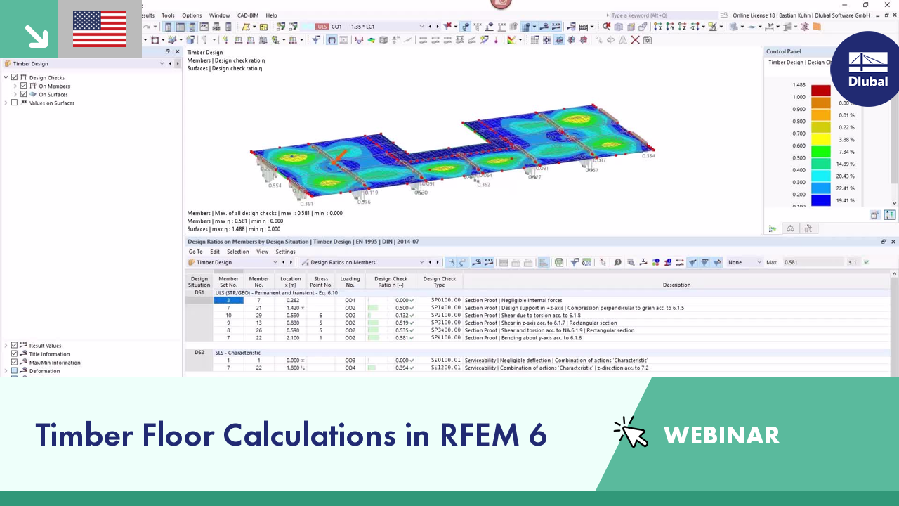
The Timber Design add-on performs the ultimate, serviceability, and fire resistance limit state design checks of timber members according to various standards.

The Structure Stability add-on performs stability analysis of structures. It determines critical load factors and the corresponding stability modes.

The modern 3D structural analysis and design program is suitable for the structural and dynamic analysis of beam structures as well as the design of concrete, steel, timber, and other materials.
The Timber Design add-on performs the ultimate, serviceability, and fire resistance limit state design checks of timber members according to various standards.

Timber design of single-span and wide-span glulam beams according to Eurocode 5 or DIN 1052

Timber design of simple, continuous, and Gerber beams with or without cantilever according to Eurocode 5 or DIN 1052

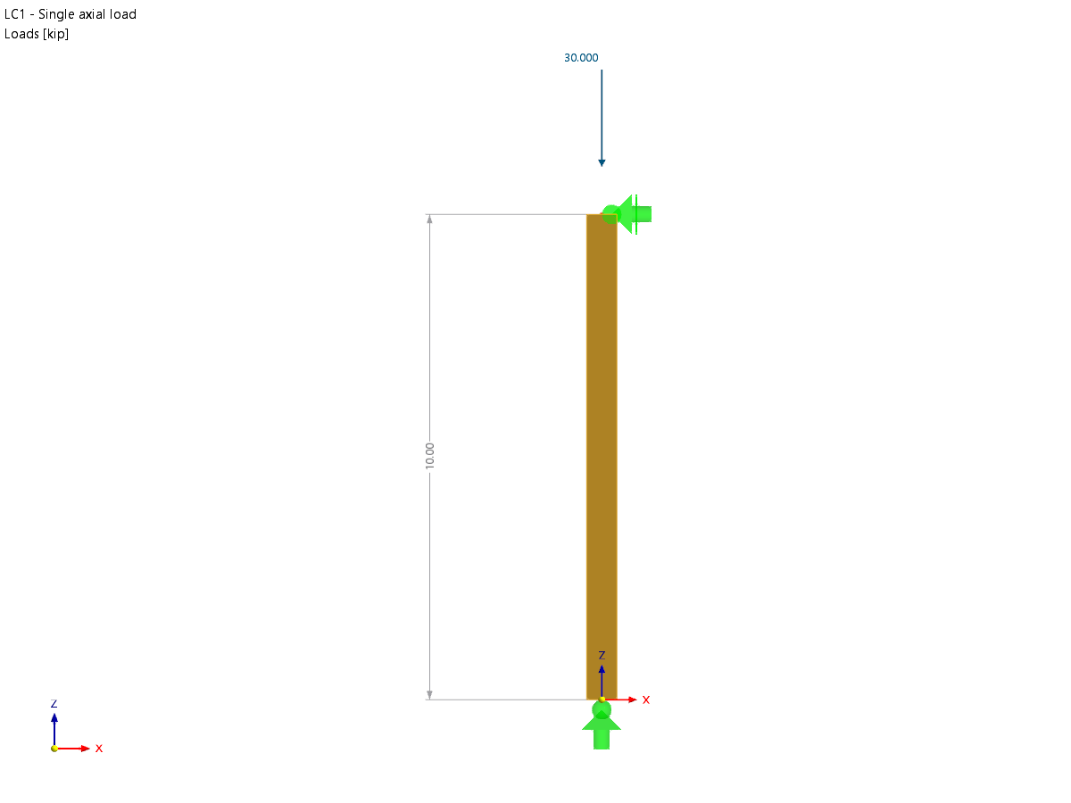
Timber design of rectangular and circular columns according to Eurocode 5 or DIN 1052

Timber design of coupled purlins and continuous beams according to Eurocode 5 or DIN 1052

Timber design of three-hinged frames with finger joint connections according to Eurocode 5 or DIN 1052

Timber design of stiffening truss bracing according to Eurocode 5 or DIN 1052

Timber design of flat, monopitch, and duopitch roofs according to Eurocode 5

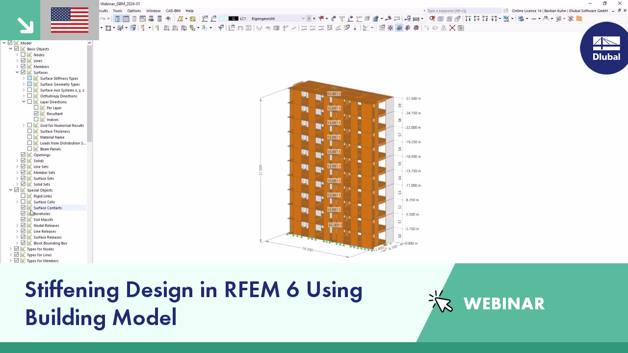
The Building Model add-on for RFEM allows you to define and manipulate a building using stories. The stories can be adjusted in many ways afterwards. The information about stories and the entire model (center of gravity) is displayed in tables and graphics.

The Concrete Design add-on allows for various design checks according to international standards. You can design members, surfaces, and columns, as well as perform punching and deformation analyses.

The Masonry Design add-on for RFEM allows you to design masonry using the finite element method. It was developed as part of the research project titled DDMaS – Digitizing the Design of Masonry Structures. The material model represents the nonlinear behavior of the brick-mortar combination in the form of macro-modeling.

The Steel Design add-on performs the ultimate and serviceability limit state design checks of steel members according to various standards.

The Nonlinear Material Behavior add-on allows you to consider material nonlinearities in RFEM for example, isotropic plastic, orthotropic plastic, isotropic damage).

The Construction Stages Analysis (CSA) add-on allows for considering the construction process of structures (member, surface, and solid structures) in RFEM.

In RFEM, the Geotechnical Analysis add-on uses properties from soil samples to determine the soil body to be analyzed. The accurate determination of soil conditions significantly affects the quality of the structural analysis of buildings.

The Modal Analysis add-on allows for the calculation of eigenvalues, natural frequencies, and natural periods for member, surface, and solid models.

The Response Spectrum Analysis add-on performs seismic analysis using multi-modal response spectrum analysis. The spectra required for this can be created in compliance with the standards or can be user-defined. The equivalent static forces are generated from them. The add-on includes an extensive library of accelerograms from seismic zones that can be used to generate the response spectra.

Using the Pushover Analysis add-on, you can analyze the seismic actions on a particular building, and thus assess whether the building can withstand an earthquake.

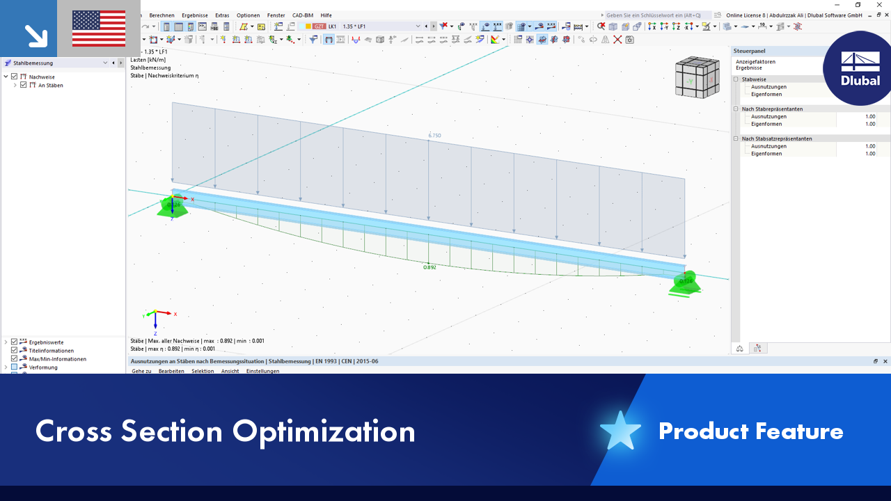
The two-part Optimization & Costs / CO2 Emission Estimation add-on finds suitable parameters for parameterized models and blocks via the artificial intelligence (AI) technique of particle swarm optimization (PSO) for compliance with common optimization criteria. Furthermore, this add-on estimates the model costs or CO2 emissions by specifying unit costs or emissions per material definition for the structural model.
Earthquakes may have a significant impact on the deformation behavior of buildings. A pushover analysis allows you to analyze the deformation behavior of buildings and compare them with seismic actions. Using the Pushover Analysis add-on, you can analyze the seismic actions on a particular building, and thus assess whether the building can withstand the earthquake.
The Response Spectrum Analysis add-on performs seismic analysis using the multi-modal response spectrum analysis. The spectra required for this can be created in compliance with the standards or can be user-defined. The equivalent static forces are generated from them. The add-on includes an extensive library of accelerograms from seismic zones that can be used to generate response spectra.
The Modal Analysis add-on allows for the calculation of eigenvalues, natural frequencies, and natural periods for member, surface, and solid models.
Concrete Design add-on allows for various design checks of members and columns according to international standards.
The Steel Design add-on performs the ultimate and serviceability limit state design checks of steel members according to various standards.

The Aluminum Design add-on performs the ultimate and serviceability limit state design checks of aluminum members according to various standards.
The two-part Optimization & Costs / CO2 Emission Estimation add-on finds suitable parameters for parameterized models and blocks via the artificial intelligence (AI) technique of particle swarm optimization (PSO) for compliance with common optimization criteria. Furthermore, this add-on estimates the model costs or CO2 emissions by specifying unit costs or emissions per material definition for the structural model.

The Stress-Strain Analysis add-on performs a general stress analysis by calculating the existing stresses and comparing them to the limit stresses.

The Torsional Warping (7 DOF) add-on allows you to consider cross-section warping as an additional degree of freedom.

The Multilayer Surfaces add-on allows you to define multilayer surface structures. The calculation can be carried out with or without the shear coupling.
The Stress-Strain Analysis add-on performs general stress analysis by calculating the existing stresses and comparing them with the limit stresses.
The Aluminum Design add-on performs the ultimate and serviceability limit state design checks of aluminum members according to various standards.
.png?mw=600&hash=49b6a289915d28aa461360f7308b092631b1446e)
The Steel Joints add-on for RFEM allows you to analyze steel connections using an FE model. The FE model is generated automatically in the background and can be controlled via the simple and familiar input of components.
The Structure Stability add-on performs the stability analysis of structures. It determines critical load factors and the corresponding stability modes.
The Torsional Warping (7 DOF) add-on allows for considering cross-section warping as an additional degree of freedom when calculating members.

The Time-Dependent Analysis (TDA) add-on allows you to consider the time-dependent material behavior of members. The long-term effects, such as creep, shrinkage, and aging, can influence the distribution of internal forces, depending on the structure.

The Form-Finding add-on finds the optimal shape of members subjected to axial forces and tension-loaded surface models. The shape is determined by the equilibrium between the member axial force or the membrane stress and the existing boundary conditions.